This thread has been locked.

If you have a related question, please click the "Ask a related question" button in the top right corner. The newly created question will be automatically linked to this question.

MSP430FR5994: [I2C] Inaccurate eUSCI description on User's Guide

Part Number: MSP430FR5994
Other Parts Discussed in Thread: MSP430F5529,

Dear MSP430 community,

I've faced a singular issue the past days that i've never faced before. I usually compliment Texas Instruments for their documentation, either for its well organized datasheets or greatly detailed User's Guides. The past couple of weeks thought have been a nightmare because of (what I believe, and please, correct me if I'm wrong) an inaccurate description of eUSCI operation while in I2C mode. User's Guide (SLAU367O) states clearly on section 32.3.5.2.1, page 829 that when on Master-Transmitter mode,

If there is no data loaded to UCBxTXBUF before the acknowledge cycle, the bus is held during the acknowledge cycle with SCL low until data is written into UCBxTXBUF.

The figure 32-12 completes this information with a nice diagram showing SCL held if TXBUF is not written, and then STT bit is cleared as soon as a ACK or NACK is received. Despite that, in my tests, using a logic analyser, I've witnessed that the above statement is not true. 

As soon as STT bit is set, eUSCI will send the 7-bit address, R/W bit, and the ACK/NACK cycle, and thus, making it hard to detect when to send a stop or the next byte of data. What would be a simple execution lock in C (after writing to TX buffer): 

// Wait until ACK/NACK is received
while(UCB1CTLW0 & UCTXSTT); 

if(UCB1IFG & UCNACKIFG) {
  // Request stop 
  // ...
}

Should be now a wait for the next TX write cycle or a stop condition at the same time. Like this:

// Wait for next TX cycle or exit if there was a NACK
while( !(UCB1IFG & UCTXIFG) & !(UCB1IFG & UCNACKIFG) );

if (UCB1IFG & UCNACKIFG) {
  // Send stop
  // ...

}

I was struggling with this because I've trusted too much TI documentation, and thought that my code was incorrect, which usually is ;). I guess this time it was the other way around.

Hope this helps others MSP430FR59xx users out there. 

Edit: Typo

  • Hi Daniel,

    Hopefully I can help here.  Would you please elaborate on these statements?

    Daniel Cafe said:

    The figure 32-12 completes this information with a nice diagram showing SCL held if TXBUF is not written, and then STT bit is cleared as soon as a ACK or NACK is received. Despite that, in my tests, using a logic analyser, I've witnessed that the above statement is not true. 

    As soon as STT bit is set, eUSCI will send the 7-bit address, R/W bit, and the ACK/NACK cycle, and thus, making it hard to detect when to send a stop or the next byte of data. What would be a simple execution lock in C (after writing to TX buffer): 

    Are you expecting that if you are in master-transmitter mode, and send a START, that the ACK/NACK cycle doesn't happen until you write to the TXBUF?  Or, are you seeing that after the ACK/NACK cycle SCL is not held until TXBUF is written?  You mentioned that you had some logic captures.  It would be great if you could post what you are seeing so that we can reference the same scenario.  Please also post your initialization code for the eUSCI_B.

    Best regards,
    Walter

  • Thank you Walter for your fast reply,

    In my interpretation of the User's Guide, the ACK/NACK cycle should not happen until we write to TXBUF. When we do, the eUSCI should then proceed to the ACK/NACK cycle so we can decide either to continue communication (in case of a ACK) of request a stop (in case of a NACK).  

    Here's how I configure my interface

        UCB1CTLW0 |= UCSWRST;       // Reset I2C interface for configuration
    
        UCB1CTLW0 =                 /* USCI - B1 configuration register */
                    UCMST         | // Master mode
                    UCSYNC        | // Synchronous mode
                    UCMODE_3      | // I2C mode
                    UCSSEL__SMCLK | // Select SMCLK
                    UCTR          | // Transmitter mode
                    UCSWRST       | // Don't release reset (yet)
                    0;
    
        UCB1CTLW1 =
                    UCCLTO_0      | // Clock low time-out select (disabled)
                    UCASTP_0      | // Automatic STOP condition generation (disabled)
                    UCGLIT_0      | // Deglitch time (50ns)
                    0;
    
        UCB1BRW = 10;               // Bit clock divider 1M/10 = 100kHz
    
        UCB1I2COA0 = OWN_ADDRESS  | // Own address
                     UCOAEN       | // Address Enable
                     0;
    
        // Configure interface ports
        P5SEL0 |=  (BIT0 | BIT1);   // Connect ports P5.0 and P5.1 to
        P5SEL1 &= ~(BIT0 | BIT1);   // eUSCI-B1, SDA and SCL, respectively
        P5DIR  &= ~(BIT0 | BIT1);   // Configure as if they are inputs
        P5REN  |=  (BIT0 | BIT1);   // Enable internal resistors
        P5OUT  |=  (BIT0 | BIT1);   // Set as pull-up
    
        UCB1CTLW0 &= ~UCSWRST;      // Clear reset bit to start operation
    

    And this is my interpretation of the User's Guide send procedure:

        UCB1I2CSA = slaveAddr;                  // Set slave addr
        UCB1CTLW0 |= UCTR | UCTXSTT;            // Request a start as a transmitter
    
        while(!(UCB1IFG & UCTXIFG));            // Wait until TXBUFF is empty
        UCB1TXBUF = *dataPtr++;                 // Send first data byte
    
        while(UCB1CTLW0 &  UCTXSTT);            // Wait for slave's response (not working on MSP430FR5994)
    
        if (UCB1IFG & UCNACKIFG) {              // If there was no response
            UCB1IFG &= ~UCNACKIFG;              // Clear NACK flag
            UCB1CTLW0 |= UCTXSTP;               // Request a stop 
            while (UCB1CTLW0 & UCTXSTP);        // And wait until stop was actually sent
            UCB1IFG  &= ~UCSTPIFG;              // Clear stop flag (not actually using this..)
            return I2C_ERROR_DEVICE_NOT_FOUND;
        } 
        else {                                  // If there was a reply from the slave, 
            while (--count) {                   // send the remaining bytes
                while(!(UCB1IFG & UCTXIFG));
                UCB1TXBUF = *(dataPtr++);
            }
        }
    
        while(!(UCB1IFG & UCTXIFG));            // Wait for the last byte to be loaded to shift reg.
        UCB1CTLW0 |= UCTXSTP;                   // Request a stop condition.
        while (UCB1CTLW0 & UCTXSTP);            // Wait until stop was sent
    
        UCB1IFG &= ~UCTXIFG;                    // Clear TX flag, because we've interrupted 
                                                // communication before sending data
    
        return I2C_SUCCESS;                     // Return with a success code (0)
    

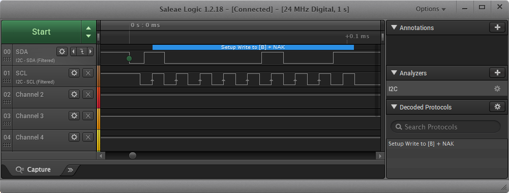
    If I set a breakpoint right after setting the STT bit (i.e. requesting a start). The interface will send this: 

    As you can see, the ACK/NACK (in this case a NACK) cycle was sent.

    That's why I'm using the double condition to detect when the ACK/NACK was actually sent. 

  • Daniel,

    I reviewed the user's guide and I can definitely understand your interpretation based on Figure 32-12. In all of my experience working with the eUSCI_B, the ACK/NACK is always clocked with the ADDR and R/W bits, but I usually load the TXBUF right away and then wait to see if the slave were to NACK for some reason (if it does, than it just dumps my data from TXBUF and it would need to be re-loaded). I'll do some digging to confirm the operational diagram in Figure 32-12. The text in 32.3.5.2.1 doesn't suggest one way or the other to me, but the operational diagram seems pretty explicit that the hold on SCL should come before the ACK/NACK bit. Usually we do a very good job with our documentation, but I'd be lying if I said a mistake has never happened! I appreciate you bringing up this inconsistency on the forum so that we can get the behavior better defined for the community here.

    Also, out of curiosity, is there a reason why you need to delay the ACK/NACK in your application? I was thinking about this, and I'm not sure what the need would be for doing so. I did see that you mentioned in the original post that this behavior makes it hard to determine whether to send the next piece of data or terminate the communication. You are already loading the first byte to go out. If a NACK occurs, that TX data should be voided and you would get the NACK flag.

    Regards,
    Walter
  • Thank you Walter,

    Could you please share your code for "wait to see if the slave were to NACK for some reason" without using interrupts, only by pooling flags? I think that's the key aspect of this issue. I've worked with the MSP430F5529 launchpad before and the USCI works exactly as the User's Guide describes (By the way, this code is derived from what I've done previously with the F5529 variant). Unfortunately, I cannot say the same for the eUSCI interface of the MSP430FR5994. The code that I posted earlier jumps the STT bit pooling, because STT is cleared before NACK is received. In other words, line 9 of the send code is pretty much useless. That's the inconsistency I've found. Reading the User's Guide, I've imagined that when the STT bit is cleared, it means that the ACK/NACK was received, and I can check the corresponding flag.

    I've first encountered this issue when writing an I2C scanner code. I wanted to send only the address to see if there was a slave present on the I2C bus. No need to send data in this case. So I needed to set the STP bit before the ACK/NACK cycle, and then wait for the ACK/NACK to check if the slave was present of not. The issue appears when there is a NACK, because the NACK will clear TXIFG (or at least, avoid it from being set), and the send code will lock on line 27.

    Answering your question.. No, I don't need to delay the ACK/NACK cycle. That will never happen because, just like you, I write to TXBUF right on the begging. I just wanted to make sure I had a precise timing in my application so I don't set the STP bit in the wrong moment.

    Anyway, this issue can be remedied by checking for either the TX flag or a NACK event right after the address frame, just like the code from my fist post.

    Let's dig this issue together to determine the correct behavior of the eUSCI interface. I have to say, I admire TI documentation. I'm only trying to make it even better. Let me know if I can help you in any way.
  • Daniel,

    I agree, let's get the behavior clarified. I usually use interrupt-driven models which changes the behavior a bit. I'll see what it looks like with a polling approach and post my results/code. You are right that the timing of setting the STP is a bit critical.

    Walter

**Attention** This is a public forum