


Part Number: MSP430G2553
Tool/software: Code Composer Studio
Hi there,
I am recently working with the Timer_A interrupt.
Hardware settup: includes a 32 kHz external crystal connected to XIN and XOUT (I am working with the launch pad). Also the RXD and TXD Jumpers are configurated for USB UART communication. Workinstation is a Laptop.
Software: The software uses the extern source to generate the ACLK signal to suply the Timer_A. I use the timer in a compare mode to generate a 1 Hz frequency and would love to see that on my oszilloskop. In generall the code works and a LED which toggles in this frequency works. For messuring I toggle P1.5 with the 1 Hz frequency as well.
Messuring settup: The P1.5 and the upper J6 GND are connected to my oszilloskop.
Problem: Funny thing is, that the toggling LED stops if i connect GND. Also I am not able to see the frequency on the oszilloskopes display. Also funny is that i am working on a laptop connected with the launchpad. If i connect my recharger to my laptop the msp led stops blinking as well. I suppose its something with the ground of the device but i have no clue how to interprete it.
Can please anybody help me with that? It drives me crazy!
An image of my messure setup:
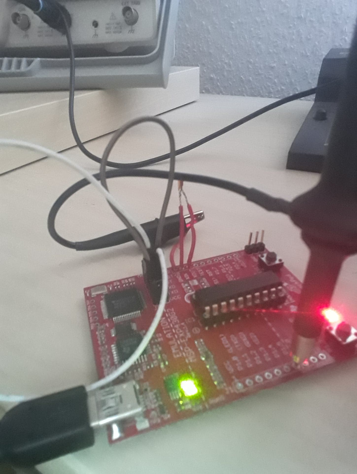

From time to time the messurement works. But as seen it shows a 1 Hz frequency even if i chose a compare value of 32000/2 so it should actually be 2 Hz. Still my setup is very sensitive about the ground pin. if i touch it or remove the ground connection to my osci, the behavior changes.
To make it complete, here my code:
#include <msp430.h>
#define LED_rot BIT0
#define LED_gruen BIT6
#define Button BIT3
#define Testpoint BIT5
bool schalter =true;
int main(void)
{
WDTCTL = WDTPW + WDTHOLD; // Stop WDT
P1DIR = LED_rot + LED_gruen + Testpoint; // P1.0 output
P1OUT = 0;
//Button setup
P1REN = Button; // Enable internal pull-up/down resistors
P1OUT = Button; //Select pull-up mode for P1.3
P1IE = Button; // P1.3 interrupt enabled
P1IES = Button; // P1.3 Hi/lo edge
P1IFG &= ~Button; // P1.3 IFG cleared
//ACLK with LFXT1CLK; 32768 Hz external crystal
BCSCTL1 = 0;
BCSCTL1 |= XT2OFF;
BCSCTL2 = 0;
BCSCTL3 =0;
BCSCTL3 |= XCAP_0;
//Compare value -> 1 Hz Toggle frequence
TACCR0 = 32768 / 2;
// C/C Register settings: no Capture; compare mode;
TACCTL0 = CM_0 + CCIE;
//Timer A setiings: Source = ACLK; Upmode; Interrupt enabled
TACTL = 0;
TACTL = TASSEL_1 + MC_1;
__bis_SR_register(GIE); // Enter LPM3 w/ interrupt
while(1)
{
}
}
// Timer A0 interrupt service routine
#pragma vector = TIMER0_A0_VECTOR
__interrupt void Timer0_A0_CCR0_ISR (void)
{
P1OUT ^= LED_rot;
P1OUT ^= Testpoint;
}
#pragma vector=PORT1_VECTOR
__interrupt void Port_1(void)
{
if ( schalter )
{
TACTL ^= MC_1;
schalter = false;
P1OUT ^= LED_gruen;
}
else
{
TACTL ^= MC_1;
schalter = true;
P1OUT ^= LED_gruen;
}
P1IES ^= Button; // P1.3 Hi/lo edge
P1IFG &=~Button; // P1.3 IFG cleared
}

