This thread has been locked.

If you have a related question, please click the "Ask a related question" button in the top right corner. The newly created question will be automatically linked to this question.

MSP432P4011: MSP432P4011

Part Number: MSP432P4011

Hi,

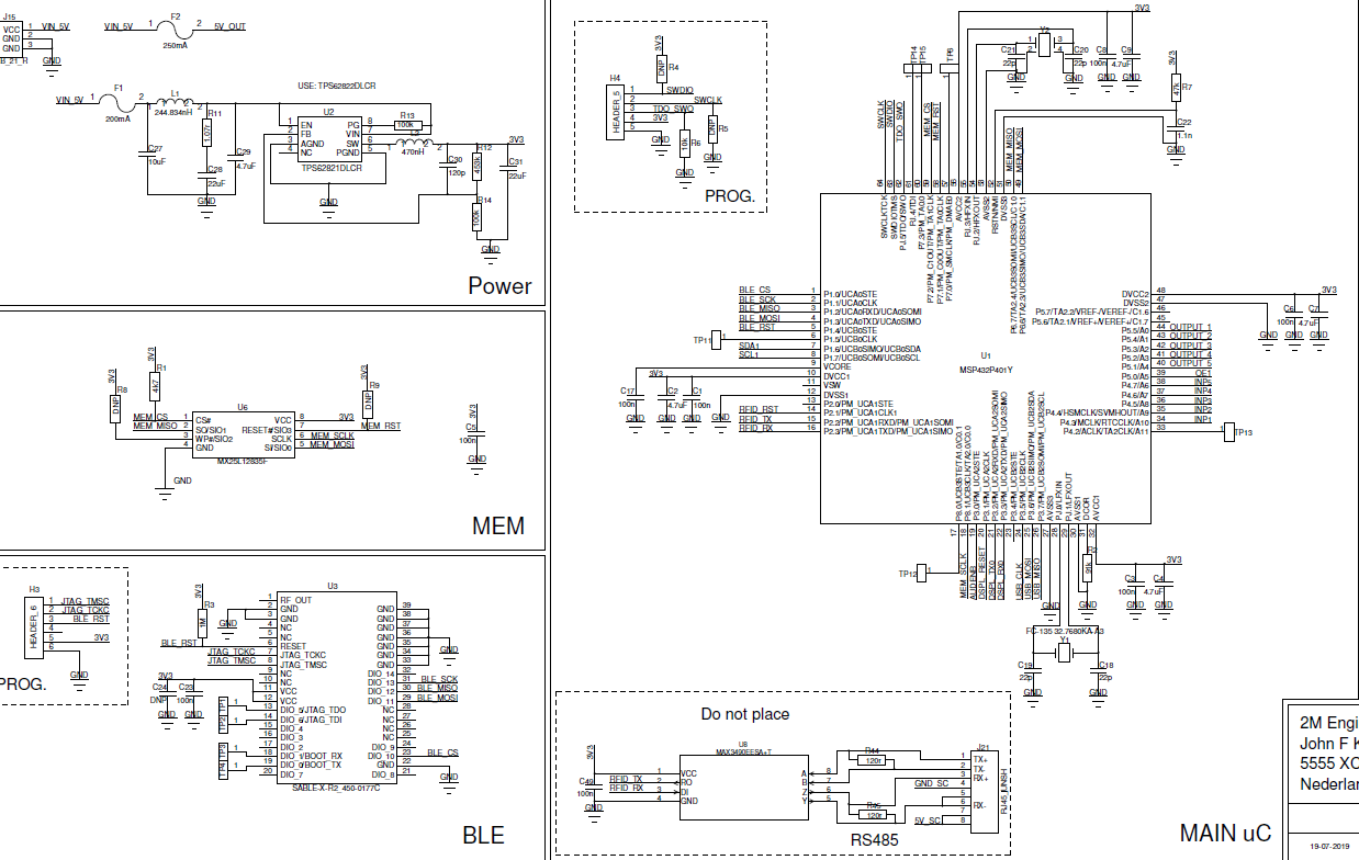
we have no trouble in flashing the MSP-EXP432P4111 (SWD), but we do have problems with lashing our custom board with the MSP432P4011. With six pcb's flashing succeed the first time, and the first time only. We populated 1 pcb(see picture) with the minimal component including the MSP432P4011RGC. Also this one succeeded only once! The pcb is 2-layers(top-bottom) and programming is done using SWD! What could be the cause?? UniFlash doen't recognize the chip AFTER the first time! No code is in the software to 'lock' the chip! Also a bit confusing is, the manual states pull-up and pulll-down for these pins but the MSP-EXP432P4111 seems to have none?

Please advise? Is this a software issue or a hardware issue(2-layers insteaad of 4-layers)

Can we chip-erase some way, and retry flashing?


  • Does that mean that the image you successfully manage to program the  MSP-EXP432P4111 with is the same as the image you are flashing your custom board with? 

  • Hi, not exactly, I used the source of the MSP432P4111 as the template and added/modified/adapted new boardfiles to suite the msp432p4011. Of course I'm cannot verify I did all this correctly since I have nothing to compare with!

    Recall first time programming seems to succeed, it even opens the debugging at 'main'. A second time it does not recognize the chip anymore! VCORE measures 59,5 mV with VCC=3V3.

    Also using UniFlash(version 5.1.0) gives no salvation!

    Regards, Laurent

  • I assume that VCORE has the expected voltage the you reach main the first time? 

    Not sure if that has a practical impact, but if you are using a  MSP432P4011, why did you start from  MSP432P4111 files? 

  • Since there are no samples from msp432p4011. Since these processors are quite similar, 4011 is 4111 without lcd! However I did notice that several files need to be changed in that case. So, you are suggesting creating an empty 4011 project and then transferring all application files from 4111 to 4011 project?

    I see that VCORE(PIN 9) is very low, in the order of 3 - 59,5 mV, way to low I guess? This  is all to low if I look in the reference manual table 5-19!

    I created the smallest empty' "new CCS project" with just a main.c using the wizard. No luck sofar!  

  • Here's also part of the schematics. We populated one pcb with only the msp432p4011 component and its required components to run! The pull-up and pull-down resistors are 10k. But I noticed that at the LaunchPad-4111 they are not present at all? I also note that Keil advises 100k instead of 10k. The TI documentation does not advise any value?

  • Could you please highlight the components you have actually mounted on the board? 

  • Hi, only all components in the square called "MAIN uC". Pull-up/pull-down upper left are all three 100k

  • - To rule out most of the potentially code issues, are you able to run the empty example from the MSP432P4011 SDK (http://dev.ti.com/tirex/explore/node?node=AAOYIurCTJ8LLIFxOLzTng__z-lQYNj__LATEST&search=debug) and see if you see the same results there. 

    But I would guess this is a hardware issue. VCore should be 1.2 V or 1.4 V dependent on mode etc. which indicate that the soldering could be not optimal. Are the components mounted by an assembly house or internally by you? 

    Are you able to probe on the board to see if you have the expected voltages on the other pins? 

  • We will do this exercise! Get back to you tomorrow!

  • Hi, if I try to run this on the MSP-EXP432P4111-LAUNCHPAD the tool nicely indicates its the wrong MCU actally naming the MSP432P4111. If I try to run on our custom hardware I'll just get an error it can't recognize the target! Tomorrow we will assemble a new pcb very precise and see what happens!

  • Any progress? 

  • We created a new board with minimum hardware for the MCU 4011. When I connected to MSFET+ADPTR and ran Uniflash it did recognize the MSP432P4011. During that process I checked the VCORE to be 1.22V, which is ok I guess! However the pull-up and pull-down of the SWDIOTMS and SWCLKTCK are stuck at 1,66V. We manage to download using CCS but, when we step through the code it 'hangs' after the second step. After that no further connection, nor recognition is possible! We use IR soldering with a pT=260C for 30 sec. Actual measured T=245C.

    What should the values of the pullup/pulldown resitors be? TI gives no values? And, should we use pullup/pulldown at all? 

    We are also confused about Table 6-87 vesrus Table 4-5.

    Get back to you later, first try to see if mcu is 'locked' 

    regards, Laurent

  • Here our schematic again of which we made the 'sample' board, in an effort to get things working! No other compoents are mounted. Power supply is external 3V3. If MSP-FET + ADPTR is used, the switch is set to 'sense'. 

    From this we need to know:

    1) are the resistors in the upper left corner (SWDIO, SWCLK and TDO_SWO required or not? If so, which value?

    2) After first power up, before any flashing, we measure VCORE = 1,22V. Is this correct?

    3) Can it be software that lockes up the MCU after being flashed the first time? We see things go wrong if we start a debug session the very first time and then try to step. After the second step it crashes and we cannot connect anymore! VCORE is just a few mV after this, each startup!

    regads, Laurent


  • 1) Read the notes to 6.12.24 in http://www.ti.com/lit/ds/symlink/msp432p4111.pdf. As you see from the schematic, only R5 is mounted with a 10 k. 

    2) Yes

    3) Sounds a bit strange. Does this happen regardless of the program you are trying to debug? Test with the empty example from the SDK if you haven't done already. 

  • Just to be sure, is this your packing material?

  • What might help! We used a IR soldering system with the following settings:

    -rise 3C/s to 180C(highest SOAK setting) and stay there for 90 seconds.
    -rise to pT 260C and stay there for 30 seconds(measured peak temperature about 245C)
    -cool down to 50C with 6C/S

    One before last pcb we did today and then tested:
    -connect GND
    -connect 3V3
    -measure VCORE --> 1.22V
    -UniFlash recognize MCU --> MSP432P4011
    -able to flash but, after flashing VCORE = 12mV

    Last pcb we did today and then tested:
    -connect GND
    -connect 3V3
    -measure VCORE --> 10mV
    -UniFlash didn't recognise MCU

    regards, Laurent

  • Does this happen regardless of the program you are trying to debug? To my knowledge it should not be possible to turn off Vcore in software (since the MCU runs on this supply) 

    Or could you by accident try to turn on the DCDC and since the VSW pn is not connected you don't get any voltage? The LDO and DCDC are placed in parallel but I don't know if the LDO is turned on if the DCDC is selected. 

  • Well, I think were converging to the real problem! I also noticed that after just soldering the component, using the IR soldering trajectory, < 260C, the VCORE can still be < 10mV, just when the MTU is powered up with 3V3. I noticed the bag which contained these MCU's was closed in 20 april 2018 and opened by us in juli 2019! It could all be caused by NOT baking them for 8 hours at 125C!

    PS: I guess that if you want to use the DCDC you need to configure it in software? Default its not! Is that correct?

    regards,

    Laurent

  • Yes, use of DCDC requires a SW setting. The reason I mentioned it was if you had a correct Vcore before flashing and not after the flashing it could have been a (far fetched) reason

    Looking forward to the result if you mount boards with devices that are prebaked. I have seen similar issues on the first packet we used on CC1120, on that pre-baking was required. 

  • Hi TER, today we tried a 'baked' msp432p4011IRGC(64-pin), and the result was the same! CCS recognised the chip, connected, downloaded the code and started the debugger to wait at 'main'. We disconnected without any further debug action. The result was the connection could not be made again and VCORE became 3,36 mV. We can mention however that the 'new' chips came from the same batch as before, dated at 20-april-2018! The board(pcb) we use is populated with only the required components for the msp432p4011. The project is based 'oad_firmware_update_MSP432P4111_tirtos_ccs' from SDK MSP432 3.30.0.13 and BLE plugin 3.20.0.24. The boardfiles were adapted as well as 

    Tomorrow we hope to receive 'new' chips from another batch! We will try again.

    regards,

    Laurent

  • Hi, I copied from an examle project, orginally "oad_firmware_update_MSP_EXP432P4111_tirtos_ccs" from SDK BLE plugin "3.20.0.24".

    I transcoded everything to match with the "MSP432P4011" which is our target! There remain a few references to MSP432P4111 in projects file I want to get rid of as well!

    Ho can I accomplish this:

    regards,

    Laurent


  • Hi, we have reached the state were we can repeatedly program and debug the hf/lf examples. I made several changes to the CUSTOM_MSP432P4011.c/.h and Board.h. I threw out everything that's not used/needed. As I saw with the syscgf only what is used is configured. Is this the right approach?

    I include the files which comply with the earlier send schematics someone might see remaining errors?

    with the predefined "_RGC_PKG_" its build for the MSP432P4011, otherwise, "x_RGC_PKG_" the MSP-EXP432P4111 LaunchPad. 

    "Board.h"

    /*
     * Copyright (c) 2017-2018, Texas Instruments Incorporated
     * All rights reserved.
     *
     * Redistribution and use in source and binary forms, with or without
     * modification, are permitted provided that the following conditions
     * are met:
     *
     * *  Redistributions of source code must retain the above copyright
     *    notice, this list of conditions and the following disclaimer.
     *
     * *  Redistributions in binary form must reproduce the above copyright
     *    notice, this list of conditions and the following disclaimer in the
     *    documentation and/or other materials provided with the distribution.
     *
     * *  Neither the name of Texas Instruments Incorporated nor the names of
     *    its contributors may be used to endorse or promote products derived
     *    from this software without specific prior written permission.
     *
     * THIS SOFTWARE IS PROVIDED BY THE COPYRIGHT HOLDERS AND CONTRIBUTORS "AS IS"
     * AND ANY EXPRESS OR IMPLIED WARRANTIES, INCLUDING, BUT NOT LIMITED TO,
     * THE IMPLIED WARRANTIES OF MERCHANTABILITY AND FITNESS FOR A PARTICULAR
     * PURPOSE ARE DISCLAIMED. IN NO EVENT SHALL THE COPYRIGHT OWNER OR
     * CONTRIBUTORS BE LIABLE FOR ANY DIRECT, INDIRECT, INCIDENTAL, SPECIAL,
     * EXEMPLARY, OR CONSEQUENTIAL DAMAGES (INCLUDING, BUT NOT LIMITED TO,
     * PROCUREMENT OF SUBSTITUTE GOODS OR SERVICES; LOSS OF USE, DATA, OR PROFITS;
     * OR BUSINESS INTERRUPTION) HOWEVER CAUSED AND ON ANY THEORY OF LIABILITY,
     * WHETHER IN CONTRACT, STRICT LIABILITY, OR TORT (INCLUDING NEGLIGENCE OR
     * OTHERWISE) ARISING IN ANY WAY OUT OF THE USE OF THIS SOFTWARE,
     * EVEN IF ADVISED OF THE POSSIBILITY OF SUCH DAMAGE.
     */
    #ifndef __BOARD_H
    #define __BOARD_H
    #ifdef __cplusplus
    extern "C" {
    #endif
    //#include <ti/drivers/ADC.h>
    //#include <ti/drivers/ADCBuf.h>
    #include <ti/drivers/GPIO.h>
    #include <ti/drivers/I2C.h>
    //#include <ti/drivers/PWM.h>
    #include <ti/drivers/SPI.h>
    #include <ti/drivers/UART.h>
    #include <ti/drivers/Watchdog.h>
    #include <CUSTOM_MSP432P4011.h>
    #define Board_initGeneral           MSP432P4011_initGeneral
    #define Board_GPIO_LED_ON           MSP432P4011_GPIO_LED_ON
    #define Board_GPIO_LED_OFF          MSP432P4011_GPIO_LED_OFF
    #define Board_GPIO_LED0             MSP432P4011_GPIO_LED1
    #define Board_GPIO_LED1             MSP432P4011_GPIO_RGBLED_RED
    #define Board_GPIO_LED2             MSP432P4011_GPIO_RGBLED_GREEN
    #define Board_GPIO_LED3             MSP432P4011_GPIO_RGBLED_BLUE
    #define Board_GPIO_BUTTON0          MSP432P4011_GPIO_S1
    #define Board_GPIO_BUTTON1          MSP432P4011_GPIO_S2
    #define Board_I2C_B0                MSP432P4011_I2CB0
    #ifndef _RGC_PKG_
    #define Board_I2C_TMP               MSP432P4011_I2CB1
    #endif
    #define Board_NVS_META              MSP432P4011_NVSMSP4320
    #define Board_NVS_OAD               MSP432P4011_NVSMSP4321
    #define Board_SD0                   MSP432P4011_SDSPI0
    #define Board_SDFatFS0              MSP432P4011_SDSPI0
    #define Board_SPI0                  MSP432P4011_SPIB0
    #define Board_SPI1                  MSP432P4011_SPIB2
    #define Board_SPI2                  MSP432P4011_SPIB3
    #define Board_SPI3                  MSP432P4011_SPIB4
    #define Board_SPI_CS1               MSP432P4011_SPI_CS1
    #define Board_SPI_CS2               MSP432P4011_SPI_CS2
    // SAP SNP UART interface
    #ifndef _RGC_PKG_
    #define Board_UART0                 MSP432P4011_UARTA2
    #else
    #define Board_UART0                 MSP432P4011_UARTA0
    #define Board_UART1                 MSP432P4011_UARTA1
    #define Board_UART2                 MSP432P4011_UARTA2
    #endif
    #define Board_WATCHDOG0             MSP432P4011_WATCHDOG
    /* Board specific I2C addresses */
    #define Board_TMP_ADDR              (0x40)
    #define Board_SENSORS_BP_TMP_ADDR   Board_TMP_ADDR
    #define Board_TPL0401_ADDR          (0x40)
    /* BLE Defines */
    #define Board_BLE_RESET              MSP432P4011_BLE_RESET
    #define Board_BLE_MRDY               MSP432P4011_BLE_MRDY
    #define Board_BLE_SRDY               MSP432P4011_BLE_SRDY
    #define Board_GPIO_TP14              MSP432P4011_GPIO_TP14
    #define Board_GPIO_TP15              MSP432P4011_GPIO_TP15
    #ifdef __cplusplus
    }
    #endif
    #endif /* __BOARD_H */
    ---------------------------------------------------------------------------------------------------------------------------------------------------------
    "CUSTOM_MSP432P4011.h"

    /*
    * Copyright (c) 2017, Texas Instruments Incorporated
    * All rights reserved.
    *
    * Redistribution and use in source and binary forms, with or without
    * modification, are permitted provided that the following conditions
    * are met:
    *
    * * Redistributions of source code must retain the above copyright
    * notice, this list of conditions and the following disclaimer.
    *
    * * Redistributions in binary form must reproduce the above copyright
    * notice, this list of conditions and the following disclaimer in the
    * documentation and/or other materials provided with the distribution.
    *
    * * Neither the name of Texas Instruments Incorporated nor the names of
    * its contributors may be used to endorse or promote products derived
    * from this software without specific prior written permission.
    *
    * THIS SOFTWARE IS PROVIDED BY THE COPYRIGHT HOLDERS AND CONTRIBUTORS "AS IS"
    * AND ANY EXPRESS OR IMPLIED WARRANTIES, INCLUDING, BUT NOT LIMITED TO,
    * THE IMPLIED WARRANTIES OF MERCHANTABILITY AND FITNESS FOR A PARTICULAR
    * PURPOSE ARE DISCLAIMED. IN NO EVENT SHALL THE COPYRIGHT OWNER OR
    * CONTRIBUTORS BE LIABLE FOR ANY DIRECT, INDIRECT, INCIDENTAL, SPECIAL,
    * EXEMPLARY, OR CONSEQUENTIAL DAMAGES (INCLUDING, BUT NOT LIMITED TO,
    * PROCUREMENT OF SUBSTITUTE GOODS OR SERVICES; LOSS OF USE, DATA, OR PROFITS;
    * OR BUSINESS INTERRUPTION) HOWEVER CAUSED AND ON ANY THEORY OF LIABILITY,
    * WHETHER IN CONTRACT, STRICT LIABILITY, OR TORT (INCLUDING NEGLIGENCE OR
    * OTHERWISE) ARISING IN ANY WAY OUT OF THE USE OF THIS SOFTWARE,
    * EVEN IF ADVISED OF THE POSSIBILITY OF SUCH DAMAGE.
    */
    /** ============================================================================
    * @file MSP432P4011.h
    *
    * @brief MSP432P4011 Board Specific APIs
    *
    * The MSP432P4011 header file should be included in an application as
    * follows:
    * @code
    * #include <MSP432P4011.h>
    * @endcode
    *
    * ============================================================================
    */
    #ifndef __MSP432P4011_H
    #define __MSP432P4011_H

    #ifdef __cplusplus
    extern "C" {
    #endif

    /* LEDs on MSP432P4011 are active high. */
    #define MSP432P4011_GPIO_LED_OFF (0)
    #define MSP432P4011_GPIO_LED_ON (1)

    /*!
    * @def MSP432P4011_GPIOName
    * @brief Enum of GPIO names on the MSP432P4011 dev board
    */
    #ifndef _RGC_PKG_
    typedef enum MSP432P4011_GPIOName {
    MSP432P4011_GPIO_S1 = 0,
    MSP432P4011_GPIO_S2,
    MSP432P4011_BLE_SRDY,
    MSP432P4011_BLE_MRDY,
    MSP432P4011_BLE_RESET,
    MSP432P4011_GPIO_LED1,
    MSP432P4011_GPIO_RGBLED_RED,
    MSP432P4011_GPIO_RGBLED_GREEN,
    MSP432P4011_GPIO_RGBLED_BLUE,
    MSP432P4011_GPIOCOUNT
    } MSP432P4011_GPIOName;
    #else
    typedef enum MSP432P4011_GPIOName {
    MSP432P4011_BLE_SRDY,
    MSP432P4011_BLE_MRDY,
    MSP432P4011_BLE_RESET,
    MSP432P4011_GPIO_TP14,
    MSP432P4011_GPIO_TP15,
    MSP432P4011_GPIOCOUNT
    } MSP432P4011_GPIOName;

    #endif

    /*!
    * @def MSP432P4011_I2CName
    * @brief Enum of I2C names on the MSP432P4011 dev board
    */
    typedef enum MSP432P4011_I2CName {
    #ifndef _RGC_PKG_
    MSP432P4011_I2CB0 = 0,
    MSP432P4011_I2CB1,
    #else
    MSP432P4011_I2CB0 = 0,
    #endif
    MSP432P4011_I2CCOUNT
    } MSP432P4011_I2CName;

    /*!
    * @def MSP432P4011_I2CSlaveName
    * @brief Enum of I2CSlave names on the MSP432P4011 dev board
    */
    typedef enum MSP432P4011_I2CSlaveName {
    MSP432P4011_I2CSLAVEB0 = 0,

    MSP432P4011_I2CSLAVECOUNT
    } MSP432P4011_I2CSlaveName;

    /*!
    * @def MSP432P4011_NVSName
    * @brief Enum of NVS names on the MSP432P4011 dev board
    */
    typedef enum MSP432P4011_NVSName {
    MSP432P4011_NVSMSP4320 = 0,
    MSP432P4011_NVSMSP4321 = 1,

    MSP432P4011_NVSCOUNT
    } MSP432P4011_NVSName;

    /*!
    * @def MSP432P4011_SDFatFSName
    * @brief Enum of SDFatFS names on the MSP432P4011 dev board
    */
    typedef enum MSP432P4011_SDFatFSName {
    MSP432P4011_SDFatFS0 = 0,

    MSP432P4011_SDFatFSCOUNT
    } MSP432P4011_SDFatFSName;

    /*!
    * @def MSP432P4011_SDName
    * @brief Enum of SD names on the MSP432P4011 dev board
    */
    typedef enum MSP432P4011_SDName {
    MSP432P4011_SDSPI0 = 0,

    MSP432P4011_SDCOUNT
    } MSP432P4011_SDName;
    /*!
    * @def MSP432P4011_SPIName
    * @brief Enum of SPI names on the MSP432P4011 dev board
    */
    typedef enum MSP432P4011_SPIName {
    MSP432P4011_SPIB0 = 0,
    MSP432P4011_SPIB2,
    MSP432P4011_SPIB3,
    MSP432P4011_SPIB4,

    MSP432P4011_SPICOUNT
    } MSP432P4011_SPIName;

    /*!
    * @def MSP432P4011_UARTName
    * @brief Enum of UART names on the MSP432P4011 dev board
    */
    typedef enum MSP432P4011_UARTName {
    MSP432P4011_UARTA0 = 0,
    #ifdef _RGC_PKG_
    MSP432P4011_UARTA1,
    #endif
    MSP432P4011_UARTA2,

    MSP432P4011_UARTCOUNT
    } MSP432P4011_UARTName;

    /*!
    * @def MSP432P4011_WatchdogName
    * @brief Enum of Watchdog names on the MSP432P4011 dev board
    */
    typedef enum MSP432P4011_WatchdogName {
    MSP432P4011_WATCHDOG = 0,

    MSP432P4011_WATCHDOGCOUNT
    } MSP432P4011_WatchdogName;

    /*!
    * @brief Initialize the general board specific settings
    *
    * This function initializes the general board specific settings.
    */
    extern void MSP432P4011_initGeneral(void);

    #ifdef __cplusplus
    }
    #endif

    #endif /* __MSP432P4011_H */

    -----------------------------------------------------------------------------------------------------------------------------------------------------------------

    CUSTOM_MSP432P4011.c

    /*
    * Copyright (c) 2017, Texas Instruments Incorporated
    * All rights reserved.
    *
    * Redistribution and use in source and binary forms, with or without
    * modification, are permitted provided that the following conditions
    * are met:
    *
    * * Redistributions of source code must retain the above copyright
    * notice, this list of conditions and the following disclaimer.
    *
    * * Redistributions in binary form must reproduce the above copyright
    * notice, this list of conditions and the following disclaimer in the
    * documentation and/or other materials provided with the distribution.
    *
    * * Neither the name of Texas Instruments Incorporated nor the names of
    * its contributors may be used to endorse or promote products derived
    * from this software without specific prior written permission.
    *
    * THIS SOFTWARE IS PROVIDED BY THE COPYRIGHT HOLDERS AND CONTRIBUTORS "AS IS"
    * AND ANY EXPRESS OR IMPLIED WARRANTIES, INCLUDING, BUT NOT LIMITED TO,
    * THE IMPLIED WARRANTIES OF MERCHANTABILITY AND FITNESS FOR A PARTICULAR
    * PURPOSE ARE DISCLAIMED. IN NO EVENT SHALL THE COPYRIGHT OWNER OR
    * CONTRIBUTORS BE LIABLE FOR ANY DIRECT, INDIRECT, INCIDENTAL, SPECIAL,
    * EXEMPLARY, OR CONSEQUENTIAL DAMAGES (INCLUDING, BUT NOT LIMITED TO,
    * PROCUREMENT OF SUBSTITUTE GOODS OR SERVICES; LOSS OF USE, DATA, OR PROFITS;
    * OR BUSINESS INTERRUPTION) HOWEVER CAUSED AND ON ANY THEORY OF LIABILITY,
    * WHETHER IN CONTRACT, STRICT LIABILITY, OR TORT (INCLUDING NEGLIGENCE OR
    * OTHERWISE) ARISING IN ANY WAY OUT OF THE USE OF THIS SOFTWARE,
    * EVEN IF ADVISED OF THE POSSIBILITY OF SUCH DAMAGE.
    */

    /*
    * ======== MSP432P4011.c ========
    * This file is responsible for setting up the board specific items for the
    * MSP432P4011 board.
    */

    #include <CUSTOM_MSP432P4011.h>
    #include <stdbool.h>
    #include <stddef.h>
    #include <stdint.h>

    #include <ti/drivers/Power.h>
    #include <ti/drivers/power/PowerMSP432.h>

    #include <ti/devices/msp432p4xx/inc/msp.h>
    #include <ti/devices/msp432p4xx/driverlib/rom.h>
    #include <ti/devices/msp432p4xx/driverlib/rom_map.h>
    #include <ti/devices/msp432p4xx/driverlib/adc14.h>
    #include <ti/devices/msp432p4xx/driverlib/dma.h>
    #include <ti/devices/msp432p4xx/driverlib/gpio.h>
    #include <ti/devices/msp432p4xx/driverlib/i2c.h>
    #include <ti/devices/msp432p4xx/driverlib/interrupt.h>
    #include <ti/devices/msp432p4xx/driverlib/pmap.h>
    #include <ti/devices/msp432p4xx/driverlib/ref_a.h>
    #include <ti/devices/msp432p4xx/driverlib/spi.h>
    #include <ti/devices/msp432p4xx/driverlib/timer_a.h>
    #include <ti/devices/msp432p4xx/driverlib/timer32.h>
    #include <ti/devices/msp432p4xx/driverlib/uart.h>
    #include <ti/devices/msp432p4xx/driverlib/wdt_a.h>

    #include <ti/drivers/dma/UDMAMSP432.h>

    #if defined(__TI_COMPILER_VERSION__)
    #pragma DATA_ALIGN(dmaControlTable, 256)
    #elif defined(__IAR_SYSTEMS_ICC__)
    #pragma data_alignment=256
    #elif defined(__GNUC__)
    __attribute__ ((aligned (256)))
    #endif
    static DMA_ControlTable dmaControlTable[16];

    /*
    * ======== dmaErrorHwi ========
    * This is the handler for the uDMA error interrupt.
    */
    static void dmaErrorHwi(uintptr_t arg)
    {
    int status = MAP_DMA_getErrorStatus();
    MAP_DMA_clearErrorStatus();

    /* Suppress unused variable warning */
    (void)status;

    while (1);
    }

    UDMAMSP432_Object udmaMSP432Object;

    const UDMAMSP432_HWAttrs udmaMSP432HWAttrs = {
    .controlBaseAddr = (void *)dmaControlTable,
    .dmaErrorFxn = (UDMAMSP432_ErrorFxn)dmaErrorHwi,
    .intNum = INT_DMA_ERR,
    .intPriority = (~0)
    };

    const UDMAMSP432_Config UDMAMSP432_config = {
    .object = &udmaMSP432Object,
    .hwAttrs = &udmaMSP432HWAttrs
    };

    /*
    * ============================= Display =============================
    */
    #include <ti/display/Display.h>
    #include <ti/display/DisplayUart.h>
    #define MAXPRINTLEN 1024

    DisplayUart_Object displayUartObject;

    static char displayBuf[MAXPRINTLEN];

    const DisplayUart_HWAttrs displayUartHWAttrs = {
    #ifndef _RGC_PKG_
    .uartIdx = MSP432P4011_UARTA0,
    #else
    .uartIdx = MSP432P4011_UARTA2,
    #endif
    .baudRate = 115200,
    .mutexTimeout = (unsigned int)(-1),
    .strBuf = displayBuf,
    .strBufLen = MAXPRINTLEN
    };

    #ifndef BOARD_DISPLAY_USE_UART_ANSI
    #define BOARD_DISPLAY_USE_UART_ANSI 0
    #endif

    const Display_Config Display_config[] = {
    {
    # if (BOARD_DISPLAY_USE_UART_ANSI)
    .fxnTablePtr = &DisplayUartAnsi_fxnTable,
    # else /* Default to minimal UART with no cursor placement */
    .fxnTablePtr = &DisplayUartMin_fxnTable,
    # endif
    .object = &displayUartObject,
    .hwAttrs = &displayUartHWAttrs
    }
    };

    const uint_least8_t Display_count = sizeof(Display_config) / sizeof(Display_Config);

    /*
    * ======== MSP432P4011_initGeneral ========
    */
    void MSP432P4011_initGeneral(void)
    {
    Power_init();
    }

    /*
    * =============================== GPIO ===============================
    */
    #include <ti/drivers/GPIO.h>
    #include <ti/drivers/gpio/GPIOMSP432.h>

    /*
    * Array of Pin configurations
    * NOTE: The order of the pin configurations must coincide with what was
    * defined in MSP432P4011.h
    * NOTE: Pins not used for interrupts should be placed at the end of the
    * array. Callback entries can be omitted from callbacks array to
    * reduce memory usage.
    */
    GPIO_PinConfig gpioPinConfigs[] =
    {
    #ifndef _RGC_PKG_
    /* Input pins */
    /* MSP432P4011_S1 */
    GPIOMSP432_P1_1 | GPIO_CFG_IN_PU | GPIO_CFG_IN_INT_RISING,

    /* MSP432P4011_S2 */
    GPIOMSP432_P1_4 | GPIO_CFG_IN_PU | GPIO_CFG_IN_INT_RISING,

    /* MSP432P4011_SRDY */
    GPIOMSP432_P2_5 | GPIO_CFG_OUT_STD | GPIO_CFG_OUT_STR_HIGH
    | GPIO_CFG_OUT_HIGH,
    /* MSP432P4011_MRDY */
    GPIOMSP432_P6_0 | GPIO_CFG_IN_PU,

    /* MSP432P4011_RESET */
    GPIOMSP432_P6_7 | GPIO_CFG_OUT_STD | GPIO_CFG_OUT_STR_HIGH
    | GPIO_CFG_OUT_HIGH,

    /* Output pins */
    /* MSP432P4011_LED1 */
    GPIOMSP432_P1_0 | GPIO_CFG_OUT_STD | GPIO_CFG_OUT_STR_HIGH
    | GPIO_CFG_OUT_LOW,

    /* MSP432P4011_RGBLED_RED */
    GPIOMSP432_P2_0 | GPIO_CFG_OUT_STD | GPIO_CFG_OUT_STR_HIGH
    | GPIO_CFG_OUT_LOW,

    /*
    * MSP432P4011_LED_GREEN & MSP432P4011_LED_BLUE are used for
    * PWM examples. Uncomment the following lines if you would like to control
    * the LEDs with the GPIO driver.
    */
    /* MSP432P4011_RGBLED_GREEN */
    GPIOMSP432_P2_1 | GPIO_CFG_OUT_STD | GPIO_CFG_OUT_STR_HIGH
    | GPIO_CFG_OUT_LOW,

    /* MSP432P4011_RGBLED_BLUE */
    GPIOMSP432_P2_2 | GPIO_CFG_OUT_STD | GPIO_CFG_OUT_STR_HIGH
    | GPIO_CFG_OUT_LOW,

    #else
    /* MSP432P4011_SRDY TP11 */
    GPIOMSP432_P1_5 | GPIO_CFG_OUT_STD | GPIO_CFG_OUT_STR_HIGH
    | GPIO_CFG_OUT_HIGH,
    /* MSP432P4011_MRDY TP12 */
    GPIOMSP432_P8_0 | GPIO_CFG_IN_PU,

    /* MSP432P4011_BLE_RESET */
    GPIOMSP432_P1_4 | GPIO_CFG_OUT_STD | GPIO_CFG_OUT_STR_HIGH
    | GPIO_CFG_OUT_HIGH,

    /* MSP432P4011_GPIO_TP14 */
    GPIOMSP432_PJ_4 | GPIO_CFG_OUTPUT | GPIO_CFG_OUT_STR_LOW
    | GPIO_CFG_OUT_HIGH,

    /* MSP432P4011_GPIO_TP15 */
    GPIOMSP432_P7_3 | GPIO_CFG_OUTPUT | GPIO_CFG_OUT_STR_LOW
    | GPIO_CFG_OUT_HIGH,

    #endif
    };

    /*
    * Array of callback function pointers
    * NOTE: The order of the pin configurations must coincide with what was
    * defined in MSP432P4011.h
    * NOTE: Pins not used for interrupts can be omitted from callbacks array to
    * reduce memory usage (if placed at end of gpioPinConfigs array).
    */
    GPIO_CallbackFxn gpioCallbackFunctions[] =
    {
    #ifndef _RGC_PKG_
    /* MSP432P4011_S1 */
    NULL,
    /* MSP432P4011_S2 */
    NULL,
    /* MSP432P4011_SRDY */
    NULL,
    /* MSP432P4011_MRDY */
    NULL,
    /* MSP432P4011_RESET */
    NULL,
    /* MSP432P4011_LED1 */
    NULL,
    /* MSP432P4011__RGBLED_RED */
    NULL,
    /* MSP432P4011_RGBLED_GREEN */
    NULL,
    /* MSP432P4011_RGBLED_BLUE */
    NULL
    #else
    /* MSP432P4011_SRDY */
    NULL,
    /* MSP432P4011_MRDY */
    NULL,
    /* MSP432P4011_BLE_RESET */
    NULL,
    /* MSP432P4011_GPIO_TP14 */
    NULL,
    /* MSP432P4011_GPIO_TP15 */
    NULL
    #endif
    };

    const GPIOMSP432_Config GPIOMSP432_config = {
    .pinConfigs = (GPIO_PinConfig *)gpioPinConfigs,
    .callbacks = (GPIO_CallbackFxn *)gpioCallbackFunctions,
    .numberOfPinConfigs = sizeof(gpioPinConfigs)/sizeof(GPIO_PinConfig),
    .numberOfCallbacks = sizeof(gpioCallbackFunctions)/sizeof(GPIO_CallbackFxn),
    .intPriority = (~0)
    };

    /*
    * =============================== I2C ===============================
    */
    #include <ti/drivers/I2C.h>
    #include <ti/drivers/i2c/I2CMSP432.h>

    I2CMSP432_Object i2cMSP432Objects[MSP432P4011_I2CCOUNT];
    #ifndef _RGC_PKG
    #define PERIPH_BASE ((uint32_t)0x40000000) /*!< Peripherals start address */
    #define EUSCI_B1_BASE (PERIPH_BASE +0x00002400) /*!< Base address of module EUSCI_B1 registers */
    #endif

    const I2CMSP432_HWAttrsV1 i2cMSP432HWAttrs[MSP432P4011_I2CCOUNT] = {
    #ifndef _RGC_PKG_
    {
    .baseAddr = EUSCI_B0_BASE,
    .intNum = INT_EUSCIB0,
    .intPriority = (~0),
    .clockSource = EUSCI_B_I2C_CLOCKSOURCE_SMCLK,
    .dataPin = I2CMSP432_P1_6_UCB0SDA,
    .clkPin = I2CMSP432_P1_7_UCB0SCL
    },
    {
    .baseAddr = EUSCI_B1_BASE,
    .intNum = INT_EUSCIB1,
    .intPriority = (~0),
    .clockSource = EUSCI_B_I2C_CLOCKSOURCE_SMCLK,
    .dataPin = I2CMSP432_P6_4_UCB1SDA,
    .clkPin = I2CMSP432_P6_5_UCB1SCL
    }
    #else
    {
    .baseAddr = EUSCI_B0_BASE,
    .intNum = INT_EUSCIB0,
    .intPriority = (~0),
    .clockSource = EUSCI_B_I2C_CLOCKSOURCE_SMCLK,
    .dataPin = I2CMSP432_P1_6_UCB0SDA,
    .clkPin = I2CMSP432_P1_7_UCB0SCL
    }
    #endif
    };

    const I2C_Config I2C_config[MSP432P4011_I2CCOUNT] = {
    #ifndef _RGC_PKG_
    {
    .fxnTablePtr = &I2CMSP432_fxnTable,
    .object = &i2cMSP432Objects[MSP432P4011_I2CB0],
    .hwAttrs = &i2cMSP432HWAttrs[MSP432P4011_I2CB0]
    },
    {
    .fxnTablePtr = &I2CMSP432_fxnTable,
    .object = &i2cMSP432Objects[MSP432P4011_I2CB1],
    .hwAttrs = &i2cMSP432HWAttrs[MSP432P4011_I2CB1]
    }
    #else
    {
    .fxnTablePtr = &I2CMSP432_fxnTable,
    .object = &i2cMSP432Objects[MSP432P4011_I2CB0],
    .hwAttrs = &i2cMSP432HWAttrs[MSP432P4011_I2CB0]
    }
    #endif
    };

    const uint_least8_t I2C_count = MSP432P4011_I2CCOUNT;

    /*
    * =============================== NVS ===============================
    */
    #include <ti/drivers/NVS.h>
    #include <ti/drivers/nvs/NVSMSP432.h>
    #include "oad_parameters.h"

    /*
    * Reserve flash sectors for NVS driver use
    * by placing an uninitialized byte array
    * at the desired flash address.
    * Place uninitialized array at base addresses
    */
    #pragma LOCATION(SNP_code, NVS_OAD_BASE);
    #pragma NOINIT(SNP_code);
    uint8_t SNP_code[OAD_REGION_SIZE];

    #pragma LOCATION(metaBuf, NVS_META_BASE);
    #pragma NOINIT(metaBuf);
    char metaBuf[OAD_META_SIZE];

    NVSMSP432_Object nvsMSP432Objects[MSP432P4011_NVSCOUNT];

    const NVSMSP432_HWAttrs nvsMSP432HWAttrs[MSP432P4011_NVSCOUNT] = {
    {
    .regionBase = (void *)metaBuf,
    .regionSize = OAD_META_SIZE,
    },
    {
    .regionBase = (void *)SNP_code,
    .regionSize = OAD_REGION_SIZE,
    },
    };

    const NVS_Config NVS_config[MSP432P4011_NVSCOUNT] = {
    {
    .fxnTablePtr = &NVSMSP432_fxnTable,
    .object = &nvsMSP432Objects[MSP432P4011_NVSMSP4320],
    .hwAttrs = &nvsMSP432HWAttrs[MSP432P4011_NVSMSP4320],
    },
    {
    .fxnTablePtr = &NVSMSP432_fxnTable,
    .object = &nvsMSP432Objects[MSP432P4011_NVSMSP4321],
    .hwAttrs = &nvsMSP432HWAttrs[MSP432P4011_NVSMSP4321],
    },
    };

    const uint_least8_t NVS_count = MSP432P4011_NVSCOUNT;
    /*
    * =============================== Power ===============================
    */
    const PowerMSP432_ConfigV1 PowerMSP432_config = {
    .policyInitFxn = &PowerMSP432_initPolicy,
    .policyFxn = &PowerMSP432_sleepPolicy,
    .initialPerfLevel = 2,
    .enablePolicy = true,
    .enablePerf = true,
    .enableParking = true
    };

    /*
    * =============================== SPI ===============================
    */
    #include <ti/drivers/SPI.h>
    #include <ti/drivers/spi/SPIMSP432DMA.h>

    SPIMSP432DMA_Object spiMSP432DMAObjects[MSP432P4011_SPICOUNT];

    /*
    * NOTE: The SPI instances below can be used by the SD driver to communicate
    * with a SD card via SPI. The 'defaultTxBufValue' fields below are set to 0xFF
    * to satisfy the SDSPI driver requirement.
    */
    const SPIMSP432DMA_HWAttrsV1 spiMSP432DMAHWAttrs[MSP432P4011_SPICOUNT] = {
    {
    .baseAddr = EUSCI_B0_BASE,
    .bitOrder = EUSCI_B_SPI_MSB_FIRST,
    .clockSource = EUSCI_B_SPI_CLOCKSOURCE_SMCLK,
    .defaultTxBufValue = 0xFF,
    .dmaIntNum = INT_DMA_INT1,
    .intPriority = (~0),
    .rxDMAChannelIndex = DMA_CH1_EUSCIB0RX0,
    .txDMAChannelIndex = DMA_CH0_EUSCIB0TX0,
    .clkPin = SPIMSP432DMA_P1_5_UCB0CLK,
    .simoPin = SPIMSP432DMA_P1_6_UCB0SIMO,
    .somiPin = SPIMSP432DMA_P1_7_UCB0SOMI,
    .stePin = SPIMSP432DMA_P1_4_UCB0STE,
    .pinMode = EUSCI_SPI_3PIN,
    .minDmaTransferSize = 10
    },
    {
    .baseAddr = EUSCI_B2_BASE,
    .bitOrder = EUSCI_B_SPI_MSB_FIRST,
    .clockSource = EUSCI_B_SPI_CLOCKSOURCE_SMCLK,
    .defaultTxBufValue = 0xFF,
    .dmaIntNum = INT_DMA_INT2,
    .intPriority = (~0),
    .rxDMAChannelIndex = DMA_CH5_EUSCIB2RX0,
    .txDMAChannelIndex = DMA_CH4_EUSCIB2TX0,
    .clkPin = SPIMSP432DMA_P3_5_UCB2CLK,
    .simoPin = SPIMSP432DMA_P3_6_UCB2SIMO,
    .somiPin = SPIMSP432DMA_P3_7_UCB2SOMI,
    .stePin = SPIMSP432DMA_P3_4_UCB2STE,
    .pinMode = EUSCI_SPI_3PIN,
    .minDmaTransferSize = 10
    },
    {
    .baseAddr = EUSCI_A1_BASE,
    .bitOrder = EUSCI_A_SPI_MSB_FIRST,
    .clockSource = EUSCI_A_SPI_CLOCKSOURCE_SMCLK,
    .defaultTxBufValue = 0xFF,
    .dmaIntNum = INT_DMA_INT2,
    .intPriority = (~0),
    .rxDMAChannelIndex = DMA_CH3_EUSCIA1RX,
    .txDMAChannelIndex = DMA_CH2_EUSCIA1TX,
    .clkPin = SPIMSP432DMA_P2_5_UCA1CLK,
    .simoPin = SPIMSP432DMA_P2_6_UCA1SIMO,
    .somiPin = SPIMSP432DMA_P2_7_UCA1SOMI,
    .stePin = SPIMSP432DMA_P2_3_UCA1STE,
    .pinMode = EUSCI_SPI_4PIN_UCxSTE_ACTIVE_LOW,
    .minDmaTransferSize = 10
    },
    {
    .baseAddr = EUSCI_B2_BASE,
    .bitOrder = EUSCI_B_SPI_MSB_FIRST,
    .clockSource = EUSCI_B_SPI_CLOCKSOURCE_SMCLK,
    .defaultTxBufValue = 0xFF,
    .dmaIntNum = INT_DMA_INT3,
    .intPriority = (~0),
    .rxDMAChannelIndex = DMA_CH5_EUSCIB2RX0,
    .txDMAChannelIndex = DMA_CH4_EUSCIB2TX0,
    .clkPin = SPIMSP432DMA_P3_5_UCB2CLK,
    .simoPin = SPIMSP432DMA_P3_6_UCB2SIMO,
    .somiPin = SPIMSP432DMA_P3_7_UCB2SOMI,
    .stePin = SPIMSP432DMA_P2_4_UCB2STE,
    .pinMode = EUSCI_SPI_4PIN_UCxSTE_ACTIVE_LOW,
    .minDmaTransferSize = 10
    }
    };

    const SPI_Config SPI_config[MSP432P4011_SPICOUNT] = {
    {
    .fxnTablePtr = &SPIMSP432DMA_fxnTable,
    .object = &spiMSP432DMAObjects[MSP432P4011_SPIB0],
    .hwAttrs = &spiMSP432DMAHWAttrs[MSP432P4011_SPIB0]
    },
    {
    .fxnTablePtr = &SPIMSP432DMA_fxnTable,
    .object = &spiMSP432DMAObjects[MSP432P4011_SPIB2],
    .hwAttrs = &spiMSP432DMAHWAttrs[MSP432P4011_SPIB2]
    },
    {
    .fxnTablePtr = &SPIMSP432DMA_fxnTable,
    .object = &spiMSP432DMAObjects[MSP432P4011_SPIB3],
    .hwAttrs = &spiMSP432DMAHWAttrs[MSP432P4011_SPIB3]
    },
    {
    .fxnTablePtr = &SPIMSP432DMA_fxnTable,
    .object = &spiMSP432DMAObjects[MSP432P4011_SPIB4],
    .hwAttrs = &spiMSP432DMAHWAttrs[MSP432P4011_SPIB4]
    }
    };

    const uint_least8_t SPI_count = MSP432P4011_SPICOUNT;

    /*
    * =============================== UART ===============================
    */
    #include <ti/drivers/UART.h>
    #include <ti/drivers/uart/UARTMSP432.h>

    UARTMSP432_Object uartMSP432Objects[MSP432P4011_UARTCOUNT];
    unsigned char uartMSP432RingBuffer[MSP432P4011_UARTCOUNT][32];

    /*
    * The baudrate dividers were determined by using the MSP432 baudrate
    * calculator
    * software-dl.ti.com/.../index.html
    */
    const UARTMSP432_BaudrateConfig uartMSP432Baudrates[] = {
    /* {baudrate, input clock, prescalar, UCBRFx, UCBRSx, oversampling} */
    {
    .outputBaudrate = 115200,
    .inputClockFreq = 24000000,
    .prescalar = 13,
    .hwRegUCBRFx = 0,
    .hwRegUCBRSx = 37,
    .oversampling = 1
    },
    {115200, 12000000, 6, 8, 32, 1},
    {115200, 6000000, 3, 4, 2, 1},
    {115200, 3000000, 1, 10, 0, 1},
    {9600, 24000000, 156, 4, 0, 1},
    {9600, 12000000, 78, 2, 0, 1},
    {9600, 6000000, 39, 1, 0, 1},
    {9600, 3000000, 19, 8, 85, 1},
    {9600, 32768, 3, 0, 146, 0}
    };

    const UARTMSP432_HWAttrsV1 uartMSP432HWAttrs[MSP432P4011_UARTCOUNT] = {
    {
    .baseAddr = EUSCI_A0_BASE,
    .intNum = INT_EUSCIA0,
    .intPriority = (~0),
    .clockSource = EUSCI_A_UART_CLOCKSOURCE_SMCLK,
    .bitOrder = EUSCI_A_UART_LSB_FIRST,
    .numBaudrateEntries = sizeof(uartMSP432Baudrates) /
    sizeof(UARTMSP432_BaudrateConfig),
    .baudrateLUT = uartMSP432Baudrates,
    .ringBufPtr = uartMSP432RingBuffer[MSP432P4011_UARTA0],
    .ringBufSize = sizeof(uartMSP432RingBuffer[MSP432P4011_UARTA0]),
    .rxPin = UARTMSP432_P1_2_UCA0RXD,
    .txPin = UARTMSP432_P1_3_UCA0TXD,
    .errorFxn = NULL
    },
    #ifdef _RGC_PKG_
    {
    .baseAddr = EUSCI_A1_BASE,
    .intNum = INT_EUSCIA1,
    .intPriority = (~0),
    .clockSource = EUSCI_A_UART_CLOCKSOURCE_SMCLK,
    .bitOrder = EUSCI_A_UART_LSB_FIRST,
    .numBaudrateEntries = sizeof(uartMSP432Baudrates) /
    sizeof(UARTMSP432_BaudrateConfig),
    .baudrateLUT = uartMSP432Baudrates,
    .ringBufPtr = uartMSP432RingBuffer[MSP432P4011_UARTA1],
    .ringBufSize = sizeof(uartMSP432RingBuffer[MSP432P4011_UARTA1]),
    .rxPin = UARTMSP432_P2_2_UCA1RXD,
    .txPin = UARTMSP432_P2_3_UCA1TXD,
    .errorFxn = NULL
    },
    #endif
    {
    .baseAddr = EUSCI_A2_BASE,
    .intNum = INT_EUSCIA2,
    .intPriority = (~0),
    .clockSource = EUSCI_A_UART_CLOCKSOURCE_SMCLK,
    .bitOrder = EUSCI_A_UART_LSB_FIRST,
    .numBaudrateEntries = sizeof(uartMSP432Baudrates) /
    sizeof(UARTMSP432_BaudrateConfig),
    .baudrateLUT = uartMSP432Baudrates,
    .ringBufPtr = uartMSP432RingBuffer[MSP432P4011_UARTA2],
    .ringBufSize = sizeof(uartMSP432RingBuffer[MSP432P4011_UARTA2]),
    .rxPin = UARTMSP432_P3_2_UCA2RXD,
    .txPin = UARTMSP432_P3_3_UCA2TXD,
    .errorFxn = NULL
    }
    };

    const UART_Config UART_config[MSP432P4011_UARTCOUNT] = {
    {
    .fxnTablePtr = &UARTMSP432_fxnTable,
    .object = &uartMSP432Objects[MSP432P4011_UARTA0],
    .hwAttrs = &uartMSP432HWAttrs[MSP432P4011_UARTA0]
    },
    #ifdef _RGC_PKG_
    {
    .fxnTablePtr = &UARTMSP432_fxnTable,
    .object = &uartMSP432Objects[MSP432P4011_UARTA1],
    .hwAttrs = &uartMSP432HWAttrs[MSP432P4011_UARTA1]
    },
    #endif
    {
    .fxnTablePtr = &UARTMSP432_fxnTable,
    .object = &uartMSP432Objects[MSP432P4011_UARTA2],
    .hwAttrs = &uartMSP432HWAttrs[MSP432P4011_UARTA2]
    }
    };

    const uint_least8_t UART_count = MSP432P4011_UARTCOUNT;

    /*
    * =============================== Watchdog ===============================
    */
    #include <ti/drivers/Watchdog.h>
    #include <ti/drivers/watchdog/WatchdogMSP432.h>

    WatchdogMSP432_Object watchdogMSP432Objects[MSP432P4011_WATCHDOGCOUNT];

    const WatchdogMSP432_HWAttrs
    watchdogMSP432HWAttrs[MSP432P4011_WATCHDOGCOUNT] = {
    {
    .baseAddr = WDT_A_BASE,
    .intNum = INT_WDT_A,
    .intPriority = (~0),
    .clockSource = WDT_A_CLOCKSOURCE_SMCLK,
    .clockDivider = WDT_A_CLOCKDIVIDER_8192K
    }
    };

    const Watchdog_Config Watchdog_config[MSP432P4011_WATCHDOGCOUNT] = {
    {
    .fxnTablePtr = &WatchdogMSP432_fxnTable,
    .object = &watchdogMSP432Objects[MSP432P4011_WATCHDOG],
    .hwAttrs = &watchdogMSP432HWAttrs[MSP432P4011_WATCHDOG]
    }
    };

    const uint_least8_t Watchdog_count = MSP432P4011_WATCHDOGCOUNT;

    regards, Laurent

**Attention** This is a public forum