This thread has been locked.

If you have a related question, please click the "Ask a related question" button in the top right corner. The newly created question will be automatically linked to this question.

MSP430F4152: Cannot comminucate with my device through SBW

Part Number: MSP430F4152

Hi,

I just created my personal circuit, and I used MSP430F4152 (48pin) as MCU. I built the PCB, and soldered the chip, but cannot communicate with MCU through SBW. I used scope to see the XIN/XOUT pins, and I saw sine waves on the pins. I also checked the SBWTDIO/SBWTCK, and scope could read digital signals from the pins. But I could not download any program into the MCU even it's very simple.

Can anyone help see if the circuit is wrong? Thanks.

Here is the ciecuit.

I refer to official design in slau278ae.pdf.

The connection with the JTAG denugger is refered from wiki.ti. processors.wiki.ti.com/.../JTAG_(MSP430)

Thank you.

  • Hi,

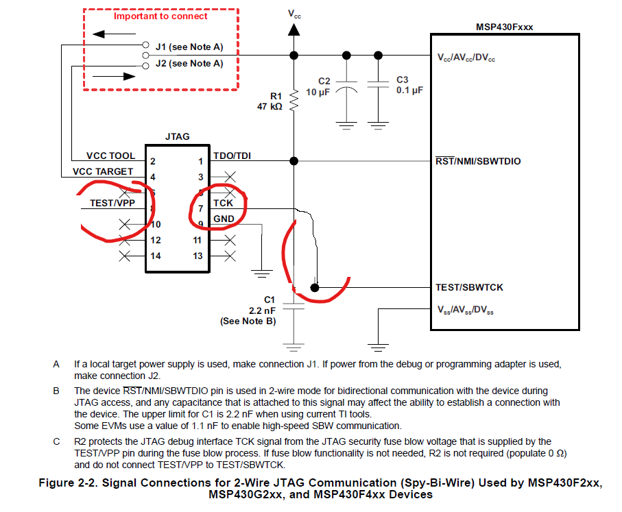
    Please remove the 330R resistor. Please see the UG, test pin from debug probe is directly connected to TEST/SBWTCK. Besides, you can see the first picture posted by you, onJP4, Pin 2 and Pin 3 are always connected.

    Eason

  • Thanks for your reply. I fixed this issue by using fly-wire to connect TEST/VPP to pin43 of MCU directly, but I did not remove 330 ohm resistor because I think that was official suggestion. But the issue still exist.

    The updated schematic is as below.

    Is there any other reason that can cause this issue? Thanks.

    BTW, the P1 and P2 are some pads on my PCB, so I soldered fly-wire to connect to JTAG cable.

  • Hi,

    The reason why I want to to remove R17 because I guest this resister will affect the timing on SBWTCK.

    Can you use a scope to chatch the wave and post it on e2e? I can check it for you.

    For SBW, it only need SBWTCLK SBWTDIO DVCC DVSS, it can work.

    Besides, you can also see C, if you don't use JTAG fuse, you can remove R2 and Test.

    Eason

  • Hi,

    I updated my circuit refer to your suggest. I removed the 330 resistor and then connect TCK to SBWTCK directly, but it still cannot find the MCU.

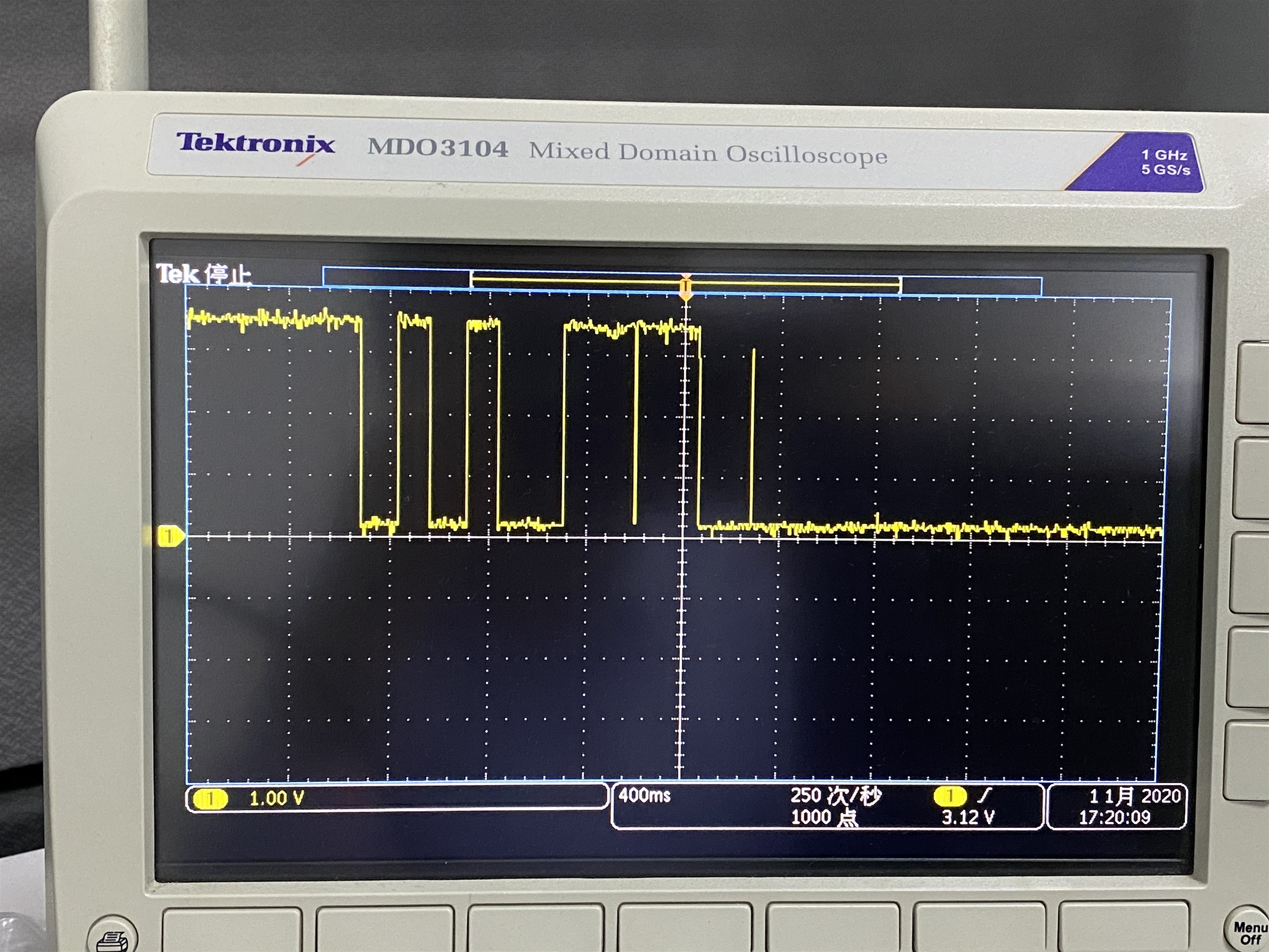
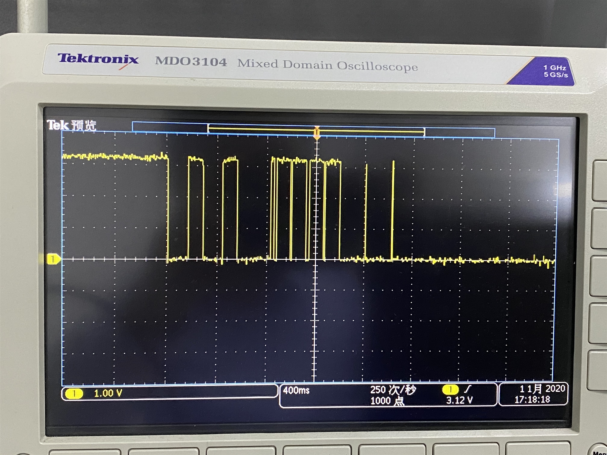
    I also use scope to capture the SBWTDI and SBWTCK signals while trying to use CCS to download.

    First image is SBWTDI, and second one is SBWTCK. I don't know if this is correct or not, but it seems that these signals are digital command.

    Thanks.

  • Hi,

    Your wave of SBW is quite strange. Please see the UG(SLAU320AE), the low phase of SBWTCK should less than 7us. When debug probe will leave SBW mode, it will keep SBWTCK low for 100us.

    Please help me double check it. What's debug probe you are using?

    Eason 

  • Hi,

    THis is what I use. I bought it from online shop.

    The environment I use is win10 x64, and CCSv9.2. CCS failed to find the msp430f4152 chip, so I also downloaded latest IAR and tried it, but also failed.

    I could configure the debug protol to SBW mode in IAR, but I did not find that configuration in CCS. The SBWTDI and SBWTCK images were captured with CCSv9.2. But I am wondering if the CCS was using 4-wire protocol when I was capturing the images since I could not configure the debug protocol in CCS.

  • Hi,

    You just make sure the hardware connection of debug interface, you don't need any software configuration.

    Here is the pin configuration of SBW. Please double check.

    Besides, do you have a launchpad? Can you test it on it? You can see the wave on the scope, the low time of  SBWTCK longer than 100us. 

    Eason 

  • Hi,

    Sorry for the delay at weekend.

    I checked the connection, and I am sure they are correct. I also saw the pin states table in datasheet, and I thought I followed it correctly. Unfortunately, I don't have a Lancupad, so I cannot try it.

    I have no idea now, so I bought another debug cable which only enables SBW protocol from online market. It's on the way now, and once it's ready I will try if it can work.

    Thanks.

  • Hi,

    Is it made by TI or third party?

    My advice is you can buy a launchpad. There is also a debugger(ez-FET) on it. You can use it as well. The problem is that you can't sure which part is wrong.(The debugger or the connection or the MSP430)

    Anyway, hope you find the root cause.

    Eason

  • Hi,

    It's made by third-party. I already got it and tested it, it could work well with my own device.

    It can now work well with IAR and CCS. I don't know the root cause, and I really feel it so strange.

    For the new SBW only cable, I only need to connect VCC, SBWTCK, SBWTDI and GND, and SBWDIO also need a pull-up resistor, but the pull-down capacitor is removed by me. It can work... I also tried old JTAG cable, it still cannot work..

    Anyway, thanks a lot for your help.

  • Hi,

    Maybe it can only work well with JTAG, not SBW.

    Eason

  • Hi,

    It's the SBW cable whick can work well. The old JTAG cable cannot work well. ^_^

  • Hi,

    Yes, I know. I mean the old JTAG cable cannot support SBW function. Have you check it before?

    For some condition, the capacitor inside the debugger will affect the SBW communication, yours are not.

    You must know that we can't make sure what happens in the the old JTAG cable, as it is not made by TI.

    Eason

  • Hi,

    Yes, I nkow it. And I will use new SBW only cable to do development in the future. 

    Thank you very much for your help.

  • OK, as this problem has been fixed, I will close this thread.

    Eason

**Attention** This is a public forum