Part Number: MSP430F5529
Other Parts Discussed in Thread: MSP430F5510, ENERGIA
Hi,
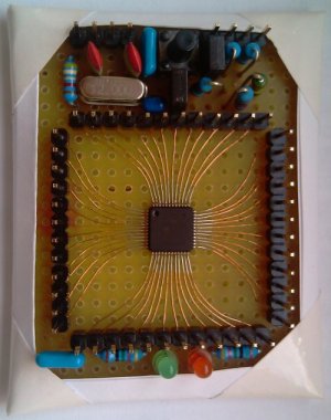
I am trying to prototype an MSP430F5529 microcontroller on a breadboard, so that I can implement it in a PCB design for a large power supply unit. I intend to use the 16 ADC channels to monitor the voltage of all the power lines (PCB manufacturing facilities at Uni are closed due to Covid-19 and I am also horrendously delayed, hence I am working on breadboard). I have implemented the 5529 on breadboard with the help of a TQFP80 adapter, soldering the chip onto that and adding the various capacitors and resistors exactly like the launchpad schematics with no differences, but I keep getting an 'Unknown file descriptor error" in the device manager of my Windows computer. I have double checked all connections and have looked at the forum posts here with users experiencing similar errors but I have been unsuccessful, the USB port is not damaged and pressing the BSL button forces a reload and redetection of the USB device but it still ends in failure. I have checked the voltage levels and my crystal oscillator and they match exactly with the voltages of the evaluation board.
To be honest I have done some research regarding the USB firmware in the flash on the microcontroller and I have seen that there is actually a dedicated programming device, a full ZIF MSP430 breakout for the board, and a JTAG programmer as an alternative to USB, do I need to purchased anything else to install the USB drivers to the flash ? None of the other forum posts seem to mention their procedure or mention that they used anything else to program it on their custom PCB. I am rather overwhelmed with the volume of methods and approaches available for programming/connection to the device, any help would be greatly appreciated.
Of course let me know if any other details are needed, my schematic is exactly the same as the launchpad down to the resistor values and I've been on this for 4 or 5 days without much progress. I am also quite experienced with circuit design and using breadboards, I have also used FTDI chips as USB com ports in exactly the same way which has been very successful.
Best Regards, Ren