This thread has been locked.

If you have a related question, please click the "Ask a related question" button in the top right corner. The newly created question will be automatically linked to this question.

CCS/MSP432P401R: SPI with F28069M

Part Number: MSP432P401R


Tool/software: Code Composer Studio

Hello,

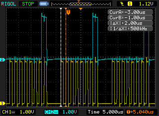
I am trying to build a SPI connection between the MSP432P401R-Launchpad (Master) and the F28069M-Launchpad (Slave).

The F28069M code works because I used it with the F28379D as Master.

I just want to send a message (sdata = 1).

I don't know if the SPI Master Config is correct.

And is my data transmit correct?

/* DriverLib Includes */
#include <ti/devices/msp432p4xx/driverlib/driverlib.h>

/* Standard Includes */
#include <stdint.h>
#include <stdbool.h>

/* Statics */
static volatile uint8_t RXData = 0;
static uint8_t TXData = 0;

//![Simple SPI Config]
/* SPI Master Configuration Parameter */
const eUSCI_SPI_MasterConfig spiMasterConfig =
{

        EUSCI_B_SPI_CLOCKSOURCE_SMCLK,             // SMCLK Clock Source
        3000000,                                   // SMCLK = DCO = 3MHZ
        500000,                                    // SPICLK = 500khz
        EUSCI_B_SPI_MSB_FIRST,                     // MSB First
        EUSCI_B_SPI_PHASE_DATA_CHANGED_ONFIRST_CAPTURED_ON_NEXT,    // Phase
        EUSCI_B_SPI_CLOCKPOLARITY_INACTIVITY_LOW, // High polarity
        EUSCI_B_SPI_3PIN                           // 3Wire SPI Mode
};
//![Simple SPI Config]

int main(void)
{
    /* Halting WDT  */
    WDT_A_holdTimer();

    //![Simple SPI Example]
    /* Selecting P1.5 P1.6 and P1.7 in SPI mode */
    GPIO_setAsPeripheralModuleFunctionInputPin(GPIO_PORT_P1,
            GPIO_PIN5 | GPIO_PIN6 | GPIO_PIN7, GPIO_PRIMARY_MODULE_FUNCTION);

    /* Configuring SPI in 3wire master mode */
    SPI_initMaster(EUSCI_B0_BASE, &spiMasterConfig);

    /* Enable SPI module */
    SPI_enableModule(EUSCI_B0_BASE);

    TXData = 0x01;

    while(1)
    {
    /* Transmitting data to slave */
    SPI_transmitData(EUSCI_B0_BASE, TXData);
    EUSCI_B0->IE &= ~EUSCI_B__TXIE;
    }
}

and adapted the Baudrate and the Bitword in the F28069M example:

//
// spi_init - 
//
void spi_init()
{

        SpibRegs.SPICTL.bit.MASTER_SLAVE = 0;
        SpibRegs.SPICTL.bit.TALK = 0; //Receiver mode enabled
        SpibRegs.SPICTL.bit.CLK_PHASE = 0;
        SpibRegs.SPICTL.bit.SPIINTENA = 1;

        // Set reset low before configuration changes
        // Clock polarity (0 == rising, 1 == falling)
        // 16-bit character
        // Enable loop-back
        SpibRegs.SPICCR.bit.SPISWRESET = 1;
        SpibRegs.SPICCR.bit.CLKPOLARITY = 0;
        SpibRegs.SPICCR.bit.SPICHAR = (8-1);
        SpibRegs.SPICCR.bit.SPILBK = 0;

        SpibRegs.SPIBRR =0x007A;
        SpibRegs.SPIPRI.bit.FREE = 1;    // Set so breakpoints don't disturb


}

  • What does it do now?

    >        EUSCI_B_SPI_PHASE_DATA_CHANGED_ONFIRST_CAPTURED_ON_NEXT,    // Phase

    spi.h says this means CKPH=0. The rule of thumb is that if the device wants CPHA=0 (as your slave appears to), you should set the MSP432's CKPH=1, so I suggest you use instead:
    >        EUSCI_SPI_PHASE_DATA_CAPTURED_ONFIRST_CHANGED_ON_NEXT,    // Phase (CKPH=1)

    Your transmit loop is sending data as fast as it can, without waiting for the transmission to complete, so some of the bytes are probably getting lost (overrun). This probably won't be evident as long as you're sending the same byte each time, but when you change that you'll notice it. You should probably replace the line that turns off TXIE (which isn't doing anything anyway) with something like:

    > while (!(EUSCI_B0->IFG & EUSCI_B_IFG_TXIFG)) /*EMPTY*/; // Wait for TXBUF to become available

  • Thanks i corrected the code,but it still doesnt work.

    Here are both codes.

    /* DriverLib Includes */
    #include <ti/devices/msp432p4xx/driverlib/driverlib.h>
    
    /* Standard Includes */
    #include <stdint.h>
    #include <stdbool.h>
    
    /* Statics */
    static volatile uint8_t RXData = 0;
    static uint8_t TXData = 0;
    
    //![Simple SPI Config]
    /* SPI Master Configuration Parameter */
    const eUSCI_SPI_MasterConfig spiMasterConfig =
    {
    
            EUSCI_B_SPI_CLOCKSOURCE_SMCLK,             // SMCLK Clock Source
            3000000,                                   // SMCLK = DCO = 3MHZ
            500000,                                    // SPICLK = 500khz
            EUSCI_B_SPI_MSB_FIRST,                     // MSB First
            EUSCI_SPI_PHASE_DATA_CAPTURED_ONFIRST_CHANGED_ON_NEXT,    // Phase
            EUSCI_B_SPI_CLOCKPOLARITY_INACTIVITY_LOW, // High polarity
            EUSCI_B_SPI_3PIN                           // 3Wire SPI Mode
    };
    //![Simple SPI Config]
    
    int main(void)
    {
        /* Halting WDT  */
        WDT_A_holdTimer();
    
        //![Simple SPI Example]
        /* Selecting P1.5 P1.6 and P1.7 in SPI mode */
        GPIO_setAsPeripheralModuleFunctionInputPin(GPIO_PORT_P1,
                GPIO_PIN5 | GPIO_PIN6 | GPIO_PIN7, GPIO_PRIMARY_MODULE_FUNCTION);
    
        /* Configuring SPI in 3wire master mode */
        SPI_initMaster(EUSCI_B0_BASE, &spiMasterConfig);
    
        /* Enable SPI module */
        SPI_enableModule(EUSCI_B0_BASE);
    
        TXData = 0x01;
    
        while(1)
        {
        /* Transmitting data to slave */
    
        SPI_transmitData(EUSCI_B0_BASE, TXData);
        while (!(EUSCI_B0->IFG & EUSCI_B_IFG_TXIFG));
        }
    }

    //
    // Included Files
    //
    #include "DSP28x_Project.h"     // Device Headerfile and Examples Include File
    
    //
    // Function Prototypes
    //
    void spi_xmit(Uint16 a);
    void spi_fifo_init(void);
    void spi_init(void);
    void error(void);
    
    Uint16 sdata = 0;  // send data
    Uint16 rdata = 0;  // received data
    
    //
    // Main
    //
    void main(void)
    {
        //
        // Step 1. Initialize System Control:
        // PLL, WatchDog, enable Peripheral Clocks
        // This example function is found in the F2806x_SysCtrl.c file.
        //
        InitSysCtrl();
    
        //
        // Step 2. Initalize GPIO: 
        // This example function is found in the F2806x_Gpio.c file and
        // illustrates how to set the GPIO to it's default state.
        //
        //InitGpio();  // Skipped for this example  
        
        //
        // Setup only the GP I/O only for SPI-A functionality
        // This function is found in F2806x_Spi.c
        //
        InitSpibGpio();
    
        //
        // Step 3. Clear all interrupts and initialize PIE vector table:
        // Disable CPU interrupts 
        //
        DINT;
    
        //
        // Initialize PIE control registers to their default state.
        // The default state is all PIE interrupts disabled and flags
        // are cleared.  
        // This function is found in the F2806x_PieCtrl.c file.
        //
        InitPieCtrl();
    
        //
        // Disable CPU interrupts and clear all CPU interrupt flags
        //
        IER = 0x0000;
        IFR = 0x0000;
    
        //
        // Initialize the PIE vector table with pointers to the shell Interrupt 
        // Service Routines (ISR).  
        // This will populate the entire table, even if the interrupt
        // is not used in this example.  This is useful for debug purposes.
        // The shell ISR routines are found in F2806x_DefaultIsr.c.
        // This function is found in F2806x_PieVect.c.
        //
        InitPieVectTable();
    
        //
        // Step 4. Initialize all the Device Peripherals:
        // This function is found in F2806x_InitPeripherals.c
        //
        //InitPeripherals(); // Not required for this example
        spi_fifo_init();	  // Initialize the Spi FIFO
        spi_init();		  // init SPI
    
        //
        // Step 5. User specific code:
        // Interrupts are not used in this example. 
        //
    
        for(;;)
        {
            while(!SpibRegs.SPISTS.bit.INT_FLAG);
            rdata = SpibRegs.SPIRXBUF;
    /*        //
            // Transmit data
            //
            spi_xmit(sdata);
    
            //
            // Wait until data is received
            //
            while(SpiaRegs.SPIFFRX.bit.RXFFST !=1)
            {
                
            }
    
            //        
            // Check against sent data
            //
            rdata = SpiaRegs.SPIRXBUF;				
            if(rdata != sdata)
            {
                error();
            }
            
            sdata++;
    */
        }
    } 	
    
    //
    // error - Step 7. Insert all local Interrupt Service Routines (ISRs) 
    // and functions here
    //
    void
    error(void)
    {
        __asm("     ESTOP0");						// Test failed!! Stop!
        for (;;);
    }
    
    //
    // spi_init - 
    //
    void spi_init()
    {
    
            SpibRegs.SPICTL.bit.MASTER_SLAVE = 0;
            SpibRegs.SPICTL.bit.TALK = 0; //Receiver mode enabled
            SpibRegs.SPICTL.bit.CLK_PHASE = 0;
            SpibRegs.SPICTL.bit.SPIINTENA = 1;
    
            // Set reset low before configuration changes
            // Clock polarity (0 == rising, 1 == falling)
            // 16-bit character
            // Enable loop-back
            SpibRegs.SPICCR.bit.SPISWRESET = 1;
            SpibRegs.SPICCR.bit.CLKPOLARITY = 0;
            SpibRegs.SPICCR.bit.SPICHAR = (8-1);
            SpibRegs.SPICCR.bit.SPILBK = 0;
    
            SpibRegs.SPIBRR =0x007A;
            SpibRegs.SPIPRI.bit.FREE = 1;    // Set so breakpoints don't disturb
    
    
    }
    
    //
    // spi_xmit - 
    //
    void
    spi_xmit(Uint16 a)
    {
        SpibRegs.SPITXBUF=a;
    }    
    
    //
    // spi_fifo_init - Initialize SPI FIFO registers
    //
    void spi_fifo_init()
    {
    //    SpiaRegs.SPIFFTX.all = 0xE040;
    //    SpiaRegs.SPIFFRX.all = 0x2044;
    //    SpiaRegs.SPIFFCT.all = 0x0;
        SpibRegs.SPIFFRX.bit.RXFFIL = 0x00;                      // 4:0    Interrupt level
        SpibRegs.SPIFFRX.bit.RXFFIENA =0;                        // 5      Interrupt enable0
        SpibRegs.SPIFFRX.bit.RXFFINTCLR = 0;                     // 6      Clear INT flag
        SpibRegs.SPIFFRX.bit.RXFFINT = 0;                        // 7      INT flag
        SpibRegs.SPIFFRX.bit.RXFFST = 0;                         // 12:8   FIFO status
        SpibRegs.SPIFFRX.bit.RXFIFORESET = 0;                    // 13     FIFO reset
        SpibRegs.SPIFFRX.bit.RXFFOVFCLR = 0;                     // 14     Clear overflow
        SpibRegs.SPIFFRX.bit.RXFFOVF = 0;                        // 15     FIFO overflow
    
        SpibRegs.SPIFFCT.all=0x0;
    
    }
    
    //
    // End of File
    //

  • What does it do now? What is it that "doesn't work"?

  • So it is transmitting data, unfortantely i cant use the osci in the university to see if the SPI package is correct.

    But the Slave isn't receiveing.

    I think the Master code isn't correct.

    The Slave code should be correct, because I tested it with another Master.

  • How do you tell that the slave never receives anything?

    When I put this code on my Launchpad, I get a normal-looking CLK/MOSI waveform. I don't have an F28069M to try.

  • Because rdata = SpibRegs.SPIRXBUF; is 0.

    I checked the Baudrate, clockphase, clockpolarity, but i dont find the problem.

    I think my SPI Configs are worng.

    const eUSCI_SPI_MasterConfig spiMasterConfig =
    {

            EUSCI_B_SPI_CLOCKSOURCE_SMCLK,             // SMCLK Clock Source
            3000000,                                   // SMCLK = DCO = 3MHZ
            1270000,                                    // SPICLK = 500khz
            EUSCI_B_SPI_MSB_FIRST,                     // MSB First
            EUSCI_SPI_PHASE_DATA_CAPTURED_ONFIRST_CHANGED_ON_NEXT,    // Phase
            EUSCI_B_SPI_CLOCKPOLARITY_INACTIVITY_LOW, // High polarity
            EUSCI_B_SPI_3PIN                           // 3Wire SPI Mode
    };
    //![Simple SPI Config]

    //
    // spi_init -
    //
    void spi_init()
    {

            SpibRegs.SPICTL.bit.MASTER_SLAVE = 0;
            SpibRegs.SPICTL.bit.TALK = 0; //Receiver mode enabled
            SpibRegs.SPICTL.bit.CLK_PHASE = 0;
            SpibRegs.SPICTL.bit.SPIINTENA = 1;

            // Set reset low before configuration changes
            // Clock polarity (0 == rising, 1 == falling)
            // 16-bit character
            // Enable loop-back
            SpibRegs.SPICCR.bit.SPISWRESET = 1;
            SpibRegs.SPICCR.bit.CLKPOLARITY = 0;
            SpibRegs.SPICCR.bit.SPICHAR = (8-1);
            SpibRegs.SPICCR.bit.SPILBK = 0;

            SpibRegs.SPIBRR = 0x007F;
            SpibRegs.SPIPRI.bit.FREE = 1;    // Set so breakpoints don't disturb
    }

  • That tells me that INT_FLAG is triggering, so it is receiving something (just not what you expect). The next exercise would be to try a different value for TXData -- 0x55 or 0xAA are usually useful values.

    Also: How is SPISTE wired?

  • SPISTE isn't used right?, but it's on Pin 3.0.

    I tried 0x55 but the Slave still reads 0.

  • How was SPISTE connected to the F28379D?

    F28069 TRM (SPRUH18H) Sec 12.2.1 ("Special Considerations") implies that a slave (always) looks at SPISTE, so it needs to be set up to read asserted (low) somehow or another. (The wording is a bit odd, but I'm extrapolating from Fig 12-5.) You might try setting P3.0 low and leaving it there.

    Background note: It appears to me that "3-wire" for the F28069 doesn't mean the same thing as "3-wire" for the MSP432. In the MSP432 it means "don't use STE", but for the F28069 it means "MISO and MOSI are shared over a single wire" (sometimes called "3-pin", but the terminology is a bit of a muddle generally).

  • Thanks a lot now I am receiving something.

    But it is another value then expected.

    You said: That tells me that INT_FLAG is triggering, so it is receiving something (just not what you expect). The next exercise would be to try a different value for TXData -- 0x55 or 0xAA are usually useful values.

    How can i correct the value?

  • Comparing F28069M TRM (SPRUH18H) Fig 12-5 and MSP432 TRM (SLAU356I) Fig 25-4, it appears you were right the first time about the CKPH=0 setting. These two appear to agree with one another, opposite to the "canonical" (if that exists) definition of CPHA.

    A clock-phase problem would scramble the bits, but wouldn't normally cause 0x55 -> 0x00. I (still) suspect SPISTE.

  • [It seems our responses "collided" and then were split by the E2E software, so I didn't see this, and you probably didn't see the CKPH post above.]

    > But it is another value then expected.

    What value are you seeing? Try setting CKPH back the way you had it originally.

  • It is switching between 256, 259, 3, 769, 513, 1, 0, when I try to send a 1.

  • Based on TRM Sec 12.3.4, I think you're supposed to ignore any bits in RXBUF outside your frame (byte) size, so AND it with 0xFF. (There's only one shift register for both Tx and Rx).

    There do appear to be a couple of 3-s where (it seems) there should be 1-s. How is CKPH set now?

  • I fogot to set CKPH = 0,

    Now I get for TXData = 0x0AA; rdata = 43690

    for TXDATA = 1, I get rdata = 1028

    for TxDATA = 55, I get 56540

  • 43690=0xAAAA, which is correct. 

    1028=0x0404 and 56540=0xDCDC, which aren't.

    I expect you're restarting the master (MSP432) for each test case. Are you restarting the slave (F28069) as well? Without having SPISTE to synchronize [Ref TRM Sec 12.2.1], it seems highly probably that restarting (only) the master will leave the slave with some leftover bits.

  • I am restarting both and get the same values.

  • 1) Are you looking at rdata using the debugger? If so, do you get different results with FREE=0 and SOFT=1? That might make SPIDAT/SPIRXBUF less of a moving-target.

    2) You might try slowing the master down, maybe by inserting something like "__delay_cycles(3000000UL);" [that's 3 million=1 second, in case I missed a 0] into the loop.

    3) You could fully-implement SPISTE -- set P3.0 low before sending the byte then set P3.0 high afterward. To do this you should change the TXIFG loop to check for (USCI_B0->STATW & USCI_B_STATW_UCBUSY) to make sure the transaction is done.

    As I mentioned, I don't have this equipment, so there's some diagnosis only you can do. I suspect neither side is acting "incorrectly", there are just different assumptions.

**Attention** This is a public forum