This thread has been locked.

If you have a related question, please click the "Ask a related question" button in the top right corner. The newly created question will be automatically linked to this question.

using ez-fet to program a different target

Other Parts Discussed in Thread: MSP430F5529, ENERGIA, MSP430F5510

I am having issues programming the MSP430F5529 on my own prototype board.   

I took a look at the MSp430F5529 LaunchPAD User guide (SLAU533c) and found the following:

  1. 2.5  Using the eZ-FET lite Emulator With a Different Target

    The eZ-FET lite emulator on the F5529 LaunchPad can interface to most MSP430 derivative devices, not just the on-board F5529 target device.

    To do this, disconnect every jumper in the isolation jumper block. This is necessary because the emulator cannot connect to more than one target at a time over the Spy-Bi-Wire (SBW) connection.

    Next, make sure the target board has proper connections for Spy-Bi-Wire. Note that to be compatible with SBW, the capacitor on RST/SBWTDIO cannot be greater than 2.2 nF. The documentation for designing MSP430 JTAG interface circuitry is the MSP430 Hardware Tools User's Guide (SLAU278).

    Finally, wire together these signals from the emulator's side of the isolation jumper block to the target hardware:

    • 3.3V

    • GND

    • 5 V (if needed)

    • SBWTDIO

    • SBWTCK

    • TXD (if the UART backchannel is to be used)

    • RXD (if the UART backchannel is to be used)

    • CTS (if hardware flow control is to be used)

    • RTS (if hardware flow control is to be used)

      This wiring can be done either with jumper wires or by designing the board with a connector that plugs into the isolation jumper block. 

Very confusing.....

The Evaluation kit does not have these signals. I have Rev 1.6 of the MSP430 F5529 LaunchPAD Evaluation kit.   It has the following:

GND

5V

3V3

RTS >>

CTS <<

RXD <<

TXD >>

SBW RST

SBW TST

THIS MEANS THE DOCUMENT IS OLD....or the PCB is wrong.

WIRING

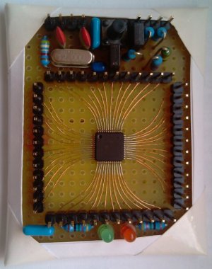
Moving on ... assuming the PCB is corect....I have wired up the following to my prototype board.

ez-fet     prototype board

gnd to god

3V3 to 3V

RXD  to  UART TX   ( Pin 55)

TXD  to  UART RX    ( Pin 51)

SBW RST  to RST  (pin 76)

SBW TST  to TEST  (pin 71)

ERROR I GET

I am using ENegia version 1.6.10E18 to connect to the target.  The command line error I am getting is the following:

command-line>:0:12: warning: missing whitespace after the macro name [enabled by default]

Sketch uses 946 bytes (0%) of program storage space. Maximum is 131,072 bytes.
Global variables use 18 bytes (0%) of dynamic memory, leaving 8,174 bytes for local variables. Maximum is 8,192 bytes.
DSLite version 6.2.1.1594
Configuring Debugger (may take a few minutes on first launch)...
Initializing Register Database...
Initializing: MSP430
Executing Startup Scripts: MSP430
Connecting...
error: MSP430: Error connecting to the target: Unknown device
Failed: Operation was aborted
the selected serial port Failed: Operation was aborted
does not exist or your board is not connected

Clearly the documentation is different then the evaluation Kit.  But I am unclear as to why this is not working.

Any help would be great.  How can I get the launchpad ez-fet to connect to my prototype board?

  • Hello Chris,

    I've moved your post to the appropriate forum for you to get support.
  • Thanks Ralph,

    I did some more poking around and I think the Silkscreen might be wrong.

    When I did a contanuity test on the SBW txt line it appear to be connected to TCK. I had to step away from troubleshooting to do other tasks so I will need to revise again later today.

    Why would the silkscreen be wrong?
    Are you guys doing design reviews when you design the launchpad boards? This is rev 1.6! Did you even test this?

    More to come....
  • Chris,

    I think there are a couple of points of clarity that I can shed on the problems you are having.

    First, the name for the SBW pins.  There is some ambiguity in the naming here because these pins are multi function pins, and it seems everyone has a slightly different version of the abbreviated name they use.  The two signal pins used for Spy-Bi-Wire programming are the RST/NMI/SBWTDIO and TEST/SBWTCK pins, specifically in the SBWTDIO and SBWTCK configurations.  Since typing or saying those full signal names becomes quickly excessive, a lot of folks refer to them as SBWTDIO and SBWTCK.  Sometimes, however, they are referred to just as TEST (or TST) and RESET (or RST), which is what the F5529LP does.  The LaunchPad does add a "SBW" label in front of the "TST" and "RST" to signify that these pins are being used in the SBW configuration.  So, in summary, SBW RST is the same signal/wire as SBWTDIO and SBW TST is the same as SBWTCK.

    On the Energia connection problem, this line in the debug message, "error: MSP430: Error connecting to the target: Unknown device" typically means that the SBW communication was never able to get a response from the target device.  Please double check the SBWTCK and SBWTDIO lines are connected correctly, as well as 3.3V and GND.  I suspect something is not connected correctly in your setup.

    Also, on the UART connections, please note that the TXD and RXD labels refer to the UART pins on the MSP430F5529 on the LaunchPad, and not the eZ-FET.  So if you need these signals for your external target, the new target MSP's TXD pin should connect to the TXD labeled jumper, and not the RXD jumper.  The same is true for the RXD signal.  This will correctly connect to the RXD and TXD pins on the eZ-FET.

    One final note.  You should be connecting to the top row on the jumpers, on the eZ-FET side, and not the target side with the F5529.

    Chris from Pinterec said:
    Are you guys doing design reviews when you design the launchpad boards? This is rev 1.6! Did you even test this?


    I helped design and review this board, so yes, I can assure you that the silkscreen is correct and that we did test this.  I have used the F5529LP as a programmer from other devices many times, and can verify that it does work.

    Mike

  • Thanks Mike,

    This helps to some degree. I did not realize it was a spy-wire connection. I was putting more time into the Uart Connection. I will just disconnect those lines and focus on SBW RST and SBW TST. It is a very weird issue as my soldering is fine.

    Is the crystal used at all during programming? I beleive the crystal is not required but I need to make sure.


    Chris
  • Chris,

    I assume you are asking about the crystal connected to the device being programmed, and not the one on the eZ-FET, correct? If so, then no, that crystal is not required for programming the device.

    Mike
  • Hi Mike,

    Ok...So this is getting pretty bad.  I tried many things during the weekend.  Here are my steps.....

    - I double checked the wire connection and it looks good.   I am connected via the following:

    gnd to gnd

    3V3 to 3V3

    SWB RTS  to RST/NMI/SBWTSIO   ( pin 76)

    SWB TST to TEST/SBWTCK  (pin 71)

     - I checked continuity and made sure it also was not shorted to anything else. 

    - I then read the document SLAU320X (Programming using the JTAG Interface)  Page 24 describes the pin out and some instructions on how to make Spy-wire work, when there are difficulties.  I shorted SBQTCK during power up and I attempted to program the device repeatable 5 -7 times. 

    - I replaced the MSP430F5529, thinking it might be damaged. 

    - I have done each of these steps on the two prototype boards I made up.  I cannot program these devices.

    - I then reconnected the jumpers on the launchpad board to make sure the ez-fet is not damaged.  I was able to successfully program the on boards MSP430F5529.

    I cannot program a different target.  It is very odd. Since this is simple not work at all I tried something else......I took a look at the old MSP-FET430UIF usb debugger interface I had from a previous project, but that is too old for this chip.   Again,  trying something different I took a look at the CCS software hoping this would help. 

    - I downloaded CCS, opened the Blink project and started the debugger.  The emulator required new firmware so I allowed that to be updated. 

    - When I attempted to load the blink program into my prototype board,  again the software tells me the target cannot be found. 

    -  Last thing I did....I attempted to load the firmware again using Energia.  Ofcourse it did not work.   But since CCS required a new firmware loaded onto the emulator I thought that could be helpful.  But ofcouse Energia just loaded its firmware back onto the emulator....and still could not find my prototype board. 

    I am at a loss.   I have not used the ez-Fit emulator or launchpad before.  I might need a little more help than the forum.   Maybe an application engineer needs to take a look. 

    How should I proceed?

  • Check your target's power supply circuits (again).

    I use the F5529 Launchpad routinely to program my target boards -- a number of different MCUs, most newer than the F5529. The only real difficulties I've had were ultimately traced to my target's power supply circuits -- wrong caps, bad solder joints, forgotten components. My observation (unscientific) is that some devices are more finicky about this than others.

    Another experiment: Can you use the eZ-FET on your Launchpad to program the target MCU on a different Launchpad? That would control for a number of variables that you (and we) probably aren't considering -- USB oddities, glitchy jumper wires and such.

  • Bruce McKenney47378 said:
    I use the F5529 Launchpad routinely to program my target boards -- a number of different MCUs, most newer than the F5529. The only real difficulties I've had were ultimately traced to my target's power supply circuits -- wrong caps, bad solder joints, forgotten components. My observation (unscientific) is that some devices are more finicky about this than others.

    I agree to Bruce and want to add that the target board needs a ~47K pull-up for the RST pin and should not have a cap to ground that is >2.2nF there.

    In addition to newer chips as target, I also tried F5529 and older chips with SBW and never had any problem.

    For download and debug, all I need to connect was 3.3V, Gnd, RST, and TEST.

    About Energia and C++, I do not see any relevance to this topic.


  • old_cow_yellow said:

    I agree to Bruce and want to add that the target board needs a ~47K pull-up for the RST pin and should not have a cap to ground that is >2.2nF there.


    Cap and pull-up combination on RST pin is only disturbance for SBW. MSP430F5529 has internal pull-up on RST pin.


    Chris, here you can see my p2p board with MSP430F5510 that is my main development board for last 5 years (sentimental reason included). And it is working OK from 1st day, till now. It was used for USB benchmarks and other "push to the limit" weird stuff. Few times connected to 5V by my mistake. My point is that MSP device is not so sensitive, and it will work fine even with poor layout. Do you have cap on VCore pin? And where is schematic of your board?

  • Thanks for your help everyone.  :)

    The probelms was a large cap on RST.  I had a 10nF to ground and a 1.3K resistor to power on RST. I simply removed the Cap and everything is working well.

    Chris  

**Attention** This is a public forum