This thread has been locked.

If you have a related question, please click the "Ask a related question" button in the top right corner. The newly created question will be automatically linked to this question.

How to Calculate PWM duty cycle .

/* Timer_A PWM Configuration Parameter */
Timer_A_PWMConfig pwmConfig =
{
TIMER_A_CLOCKSOURCE_SMCLK,  
TIMER_A_CLOCKSOURCE_DIVIDER_1,
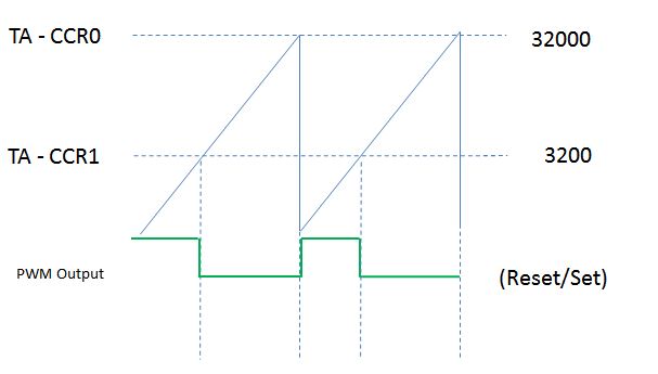
32000,
TIMER_A_CAPTURECOMPARE_REGISTER_1,
TIMER_A_OUTPUTMODE_RESET_SET,
3200
};

for Example SMCLK=64khz

Can you explain how time period and duty cycle is calculated.

  • Moving it to the MSP Forum.
  • Hi Praveen,

    Looking at Section 24.4.2.11 of the MSP432 Peripheral Driver Library User's Guide we can see a detailed explanation of the struct Timer_A_PWMConfig.

    From the struct above going from top to bottom:

    • TIMER_A_CLOCKSOURCE_SMCLK 
      • Means SMCLK is being provided to Timer-A 
    • TIMER_A_CLOCKSOURCE_DIVIDER_1
      • Means the SMCLK being provided is being divided by 1
    • 32000
      • Means the value placed in TAxCCR0 or the period of the PWM signal
        • 32000/64kHz = 0.5 seconds
    • TIMER_A_CAPTURECOMPARE_REGISTER_1
      • Decides which capture compare register will hold the PWM duty cycle value
      • In this case its TAxCCR1
    • TIMER_A_OUTPUTMODE_RESET_SET
      • Decides the output mode of the Timer's PWM output
      • In this case it is Reset/Set
        • This means the PWM signal will be reset when TimerA counts to TAxCCR1 and set when it counts to TAxCCR0
    • 3200
      • This value determines the PWM duty cycle
      • In this example it is placed in TAxCCR1

    Now that we know all the parameters of the struct we can do some math to determine the duty cycle. The setup would look something like the image below:

    So to determine the duty cycle in this example you would take TAxCCR1/TAxCCR0  = 3200/32000 = 10% duty cycle

    Hope this helps and let me know if you have anymore questions.

    Best regards, 

    Caleb Overbay

  • One more thing to ask ,how many pins that PWM supports in msp432p401R
  • Hi Praveen,

    Are you asking how many PWM outputs can the MSP432P401R support? 

    This device has 4 Timer-A instances (TA0, TA1, TA2, TA3) each with five capture/compare registers. Typically CCR0 is always used for the period so that effectively makes 4 capture/compare registers available for PWM.

    So each timer can support 4 PWM outputs for a total of 16 PWM outputs all together.

    Best regards, 
    Caleb Overbay

  • Hi Caleb,
    Is it possible to generate all the 4 PMW output at a time or one at a time .
    Thanks &regards
    Praveen
  • Hi Praveen, 

    It is possible to generate all 4 on a single timer instance at the same time. However, since CCR0 sets the period for all PWM outputs for a given timer instance, all 4 signals would have the same frequency. If the 4 outputs need to have different frequencies, then you would need to use multiple timer instances. 

    Best regards, 

    Caleb Overbay

  • Hi Caleb,
    To configure PWM for different pins is it required to have different capture and compare register.And i am trying generate PWM in two different pins so how should i configure .

    Thanks & Regards
    Praveen.
  • Hi Praveen,

    If you're trying to create two PWM signals with the same frequency you could use the same Timer-A instance for both.

    You would need to setup two separate Timer_A_PWMConfig structs with the same period. Then in one set TACCR1 to the desired duty cycle. Then in the other, set TACCR2 to the other PWM signals desired duty cycle. Configure the rest of the struct as desired, eg the output mode.

    Then you would need to setup the GPIO to act as outputs for the TACCRx registers. You can find the appropriate pins and configurations in the device datasheeet. Also the example you pulled the code snippet above from would be a great place to start when working on this.

    Best regards,
    Caleb Overbay

**Attention** This is a public forum