This thread has been locked.

If you have a related question, please click the "Ask a related question" button in the top right corner. The newly created question will be automatically linked to this question.

MSP430FR2633: MAPPING PORTS TO SENSORS

Part Number: MSP430FR2633


I am creating four 4 sensor touch faders on a board and have come accross an issue which doesnt seem to be covered in the documentation.

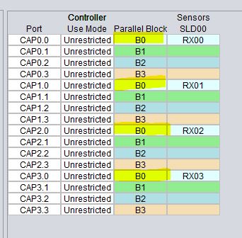
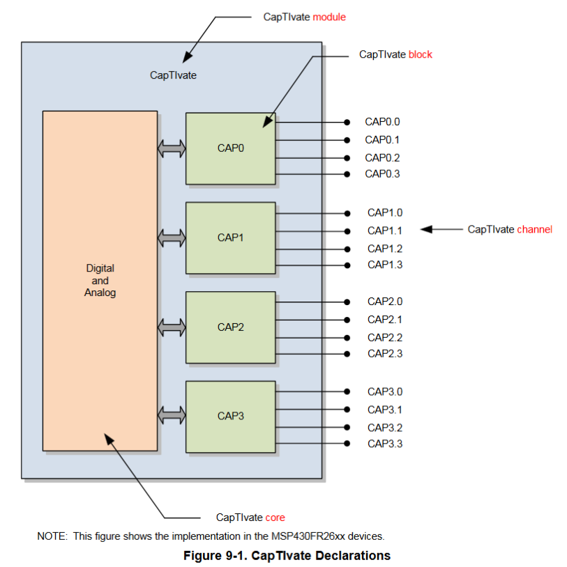
How do you connect the sensors to the ports i.e. if you have a 4 sensor fader ...do you connect to a single block (i.e. 1.0, 1.1, 1.2, 1.3) or accross blocks (i.e. 1.0, 2.0, 3.0, 4.0) or even "does it matter"

I just cant find anything that covers this, I know its simple but I still need to get it right. Any pointers to the documentation would be great

Thanks

  • Hi Sean,

    Can you clarify a few points:

    • When you say fader are you referring to sliders?
    • When you say a 4 sensor touch fader, are you saying that a single fader is made up of 4 elements?
      • Or are you saying you have 4 faders, each made of multiple elements?

    Assuming you mean a slider made up of 4 elements, you should connect each element to the same block. For example, the default slider that pops-up in CapTIvate Design center shows it is made up of four elements connected to block 3 (CAP0.3, CAP1.3, CAP2.3, and CAP3.3)

    Best regards, 
    Caleb Overbay

  • Sorry should have got my terminology right, and for simplicity lets just say a smple single slider made of 4 elements using self-capacitance. Apologies for seeking clarification but I realise my question was open to misinterpretation. Should each of these elements return to the same block or to different blocks. I did the auto-configure in design centre and it spread the elements over the four blocks i.e.
    element_0 >port CAP0.0
    element_1 >port CAP1.0
    element_2 >port CAP2.0
    element_3 >port CAP3.0

    I also noted on my scope that the sample periods for the above are concurrent, so am assuming the software uses all these results to create a single "output value" for the slider

    or have I got it all wrong?
  • Hi Sean,

    CAP0.0, CAP1.0, CAP2.0, and CAP3.0 are all part of block 0 (B0):

    I think you're confusing consecutive pins with a block. Either way, I recommend following the auto-assigned values of the Design Center. It's done this way so that all values in that block are sampled at the same time (as you saw on your scope). Then a single output value is created from these 4. 

    Best regards, 

    Caleb Overbay

  • Caleb, many thanks for that...you were indeed correct I had got the ports confused with the blocks, glad I checked...rather look a fool now rather than after we got the boards done. That all said this really could do with a bit of clarification in the documentation as I couldnt find anything that specified this. Was I looking in the wrong place?
  • Hi Sean,

    From what I can tell, this isn't very straightforward in our documentation. I'll be passing this feedback on to our CapTIvate team.

    In the Design Process section of the CapTIvate Technology Guide, we mention that the Design Center will automatically choose the optimal pin assignments between the target MCU and the sensors. Most customer's use this auto-configuration feature. 

    Thanks for bringing this to our attention and I'm glad I could help.

    Best regards, 
    Caleb Overbay

  • Sean,

    Thanks for the feedback on this topic.  I agree with you and Caleb, it's not obvious why you might choose to connect your sensors to pins one way versus the other, outside of what the CapTIvate Design Center auto-assigns.  Typically we recommend using the auto-assign tool unless the board has special requirements.

    Just to ensure that you are clear on the terminology, here is a quick explanation:

    The MSP430FR2633 has 16 CapTIvate-connected pins.  Those 16 pins are muxed into 4 CapTIvate measurement engines, or measurement "blocks".  You can think of this as being similar to a device that has 4 ADC's each with a 4:1 input mux, versus 1 ADC with a single 16:1 input mux.  Why have the complexity of multiple measurement blocks?  We have implemented 4 blocks to speed up measurement time and to improve slider/wheel sensitivity, linearity and noise immunity by measuring all elements in the slider at the same point in time.  The CapTIvate pin naming convention is CAPx.y, where 'x' is the measurement block and 'y' is the pin on that block.  Thus, CAP1.2 means that the pin is muxed as the pin 2 on measurement block 1.  The Family User's Guide shows the mapping in a visual way, as shown below.  This image should be included in the CapTIvate Technology Guide as well- I will see that it does get added to the next release.

    )

    It should be obvious at this point that in order to measure a slider with all 4 elements in parallel, you want to take one pin from each measurement block.  For example, a given slider should take CAP0.0, CAP1.0, CAP2.0, and CAP3.0.  This is the CapTIvate Design Center default behavior when using Auto-Assign.  The part that I imagine may have been confusing for you is that the CapTIvate Design Center has a concept of a "parallel block" which is actually the opposite of a measurement block.  "Parallel block" in the CapTIvate Design Center refers to a group of pins that can be measured in parallel.  It associates by default CAP0.0, CAP1.0, CAP2.0, and CAP3.0 as being "parallel scan capable".  This means that physically, they are on 4 separate measurement blocks.  A better word in the CapTIvate Design Center really would be "parallel group" to avoid confusion with the "measurement block" concept, as shown above.

    I would like to point out that you will be able to measure your sliders in either configuration (CAP0.0, CAP1.0, CAP2.0, CAP3.0, OR CAP0.0, CAP0.1, CAP0.2, CAP0.3).  However, you will get much better performance in terms of sensitivity, linearity, and response time if you implement one pin from each block (CAP0.0, CAP1.0, CAP2.0, CAP3.0), as the Auto-Assign does.

    I will file enhancements against the CapTIvate Design Center to add the following:

    1. Update the "parallel block" column title to say "parallel group"

    2. Add a pin selection methodology section to the CapTIvate Technology Guide

    Thank you for your valuable feedback!

    Best regards,

    Walter

  • Walter & Caleb, huge thank you for the help
    Can I ask one more question that has been troubling me, the P2.2 Sync connection...what is this used for? I note on the schematics for the Dev-Kit boards that this is not used and I just feel uncomfortable leaving an unused pin because I dont understand it. Its fine just pointing me to the right place in the documentation...in case its a case of RFM..but I couldnt find anything. Thanks again
  • Sean,


    The sync pin lets you pend the start of each conversion based on a low-to-high or high-to-low edge on an external pin.  This is useful if, for example, you wanted to control exactly when the conversion starts via a hardware mechanism or some external circuit.  For example, you could synchronize multiple devices via some external trigger; or, you could trigger the start-of-conversion based on an AC mains zero-crossing in a noisy environment.  This functionality is not typically used.


    It is selectable individually for each sensor in the CapTIvate Design Center if you enable "Advanced" execution mode by going to Options->Features.  Then you will see the "Input Sync" parameter under the conversion control tab for a sensor.  As I mentioned earlier, you most likely do not need this functionality.  By default, the CapTIvate starter software project does not mux the SYNC functionality on the SYNC pin, so that pin behaves just like a normal GPIO (P2.2 on the MSP430FR2633).  So, if you don't change the starter project, it will just be defaulted to output low.

    Regards,
    Walter

  • Many thanks, this clarifies it. Can I make a suggestion on the documentation (for other newbies to Capacitive Touch). It would really help if you could treat the self-capacitance and mutual-capacitance subjects seperately as mixing two essentially different and sometimes even contradictory technologies together severely complicates the learning process. Maybe an introduction that gives an overview of the technologies..just enough to make a design decision then go into the details. No criticism here, I've written enough manuals to know how difficult it is and generally the TI documentation is very good. Just a suggestion.
  • Sean,


    Thanks for the candid feedback on the tools, it is always appreciated!

    Walter

**Attention** This is a public forum