Part Number: EVM430-F6736
Hi,
We had recently purchased the EVM and when we powered it up, nothing got displayed in the LCD. We doubted the EVM to be not programmed and hence loaded the project(as in SLAA517E). The board got programmed, the LCD didn't come up but other parts of the program were working(checked through debugger). We doubted the LCD and wrote a simple program to check if the LCD and that worked(the LCD came up). We debugged a bit in the application code mentioned in SLAU517e and observed the following:
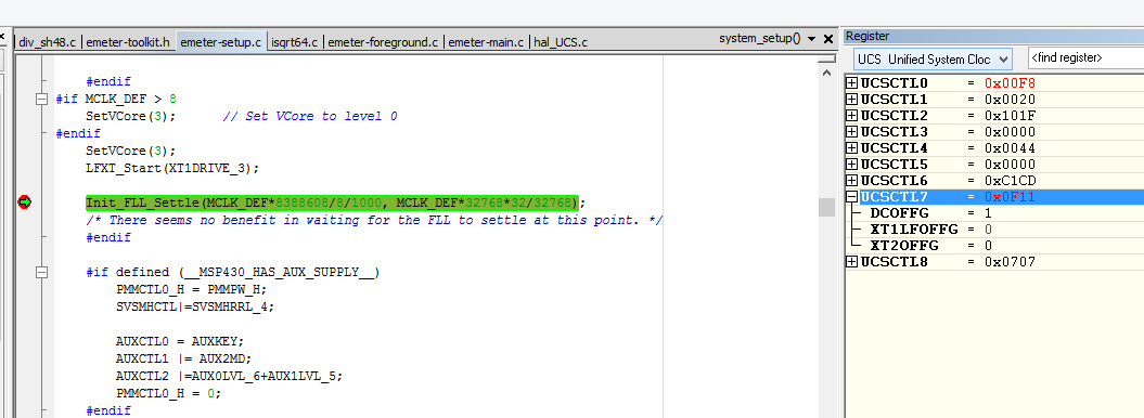
1. If we comment LFXT_Start() called in system_setup() function then everything seems to work normal(including the LCD).
2. The DCO fault flag is always set when the program is running even if we clear it.(validated through debugger)
It would be helpful if anyone can provide some insight.
Thanks & Regards
Shahul