This thread has been locked.

If you have a related question, please click the "Ask a related question" button in the top right corner. The newly created question will be automatically linked to this question.

TM4C1294NCPDT: Ethernet with WIZnet magjack not working

Part Number: TM4C1294NCPDT
Other Parts Discussed in Thread: ALLIGATOR

Hi,

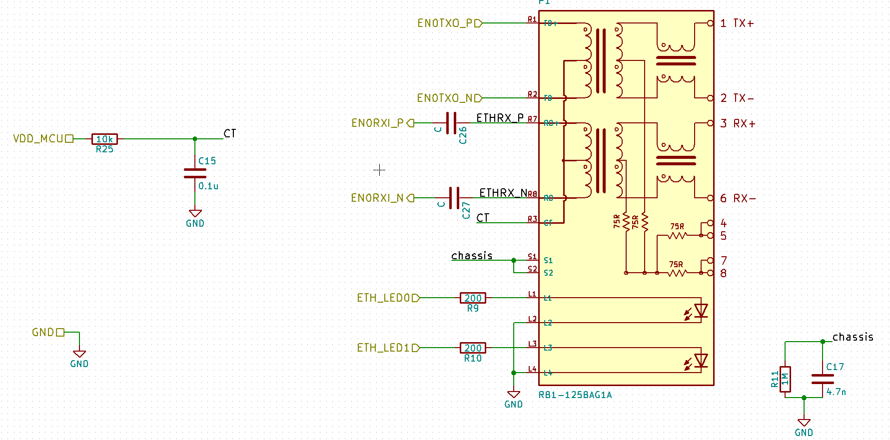
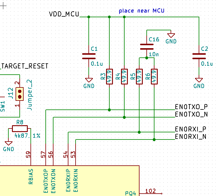
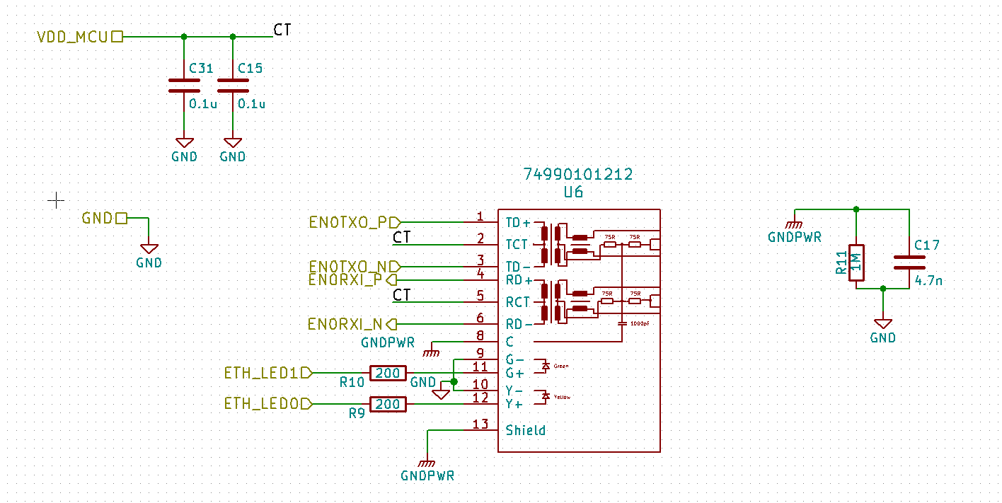
using the TM4C1294XL board I can successfully connect to my local network via ethernet. Now with my prototype system ethernet does not work (no dhcp lease, looks like no connection at all). As magjack I use a RB1-125BAG1A from WIZnet.

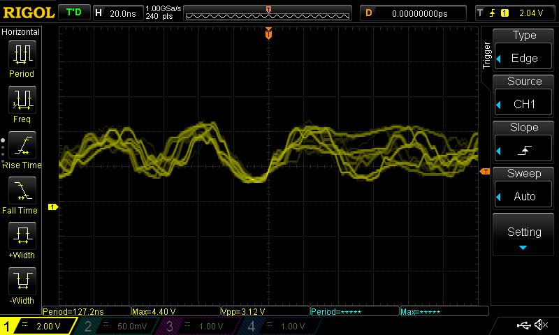
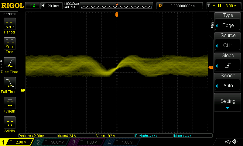
Is there anything wrong with the wiring (screenshots attached)? I have 2 prototypes which show the exact same problem.

Best regards,
LeChuck

  • The recommended circuit in the System Design Guidelines for the TM4C129x Family of Tiva™ C Series Microcontrollers is:

    And the description of the termination resistors is:

    4.1.1 Termination Resistors

    Four pull-up resistors are required for terminating and biasing the Ethernet transceivers. Refer to R40, R41, R42 and R37 in Figure 29. These resistors should be connected from the EN0TXOP, EN0TXON, EN0RXIP, and EN0RXIN signals to +3.3 V. The specified value for these resistors is 50 Ω. The recommended, commonly available value is 49.9 Ω, 1%. Do not use resistors with a tolerance greater than 1%. Resistor power dissipation is low because the peak voltage on the resistor is only approximately 1 V in 100 Mbps mode and 2.5V in 10 Mbps mode. Small, 0402 (1005 metric) surface-mount resistors have an acceptable power rating.

    Comparing your schematic to the system design guideline shows:

    1) In your schematic R5 and R6 on EN0RXI_P and EN0RXI_N are not shown as pulled up to VDD_MCU. I.e. think there is a missing connection to VDD_MCU on the net which joins R5, R6 and C16.

    2) In your schematic has R25 which is a 10K series resistor between VDD_MCU and the centre-tap of the transformer which is not shown in the system design guidelines. Not sure if that is significant.

    Can you make a mod to add a connection between VDD_MCU and the the net which joins R5, R6 and C16 to see if that enables communication?

  • Chester Gillon said:
    Can you make a mod to add a connection between VDD_MCU and the the net which joins R5, R6 and C16 to see if that enables communication?

    I have only just noticed, that while the System Design Guidelines for the TM4C129x Family of Tiva™ C Series Microcontrollers shows the transformer is DC coupled to the ENORXIN and ENORXIP, the schematics show the WIZnet magjack as AC coupled via C26 and C27 (the values which are not shown on the schematic).

    What was the reason for differing from the System Design Guidelines?

  • HI Chester,

    Do agree caps C26, C27 are depicted as AC coupled into RXD differential pair - perhaps were intend as bypass caps to ground???  Anyway good to see you in TM4C forum!

  • Thank you for your suggestions. I modified the circuit according to both your suggestions, but the problem persists.

  • I'm no help in this area - yet KNOW that (many) are asking, 'From where did the 'Pirate' evolve?

    As a 'last ditch' diagnosis - could you not, 'Probe & Scope Cap' each/every critical pin - in the attempt to discern (some) meaningful signal or level difference?    (i.e.  Brutally (exhaustingly)  'compare/contrast'  between 'Working' and 'Non-Working' boards!)     Agreed that if the board is 'too non-working' - such comparative analysis - (somewhat) suffers...

    Yet as all sailors (I am one) know ... 'ANY' Port (or diagnostic method) in a Storm - and storm clouds & high winds  buffer your (pirate) craft...

  • It would seem R5, R6 have no 3v3 bias, also take part in AC coupled diff pair conspiracy - no pirate would welcome on board. 

  • BP101 said:
    No pirate would welcome on board. 

    Mon  ami  -  'Might it TAKE One ...  to KNOW One?'

  • Tried to give it the 3V3 bias and tried both AC and DC coupling - no difference.
  • Forget the AC coupling EMAC0 will never work that way if ever with non vendor approved magnetics RJ45. Notice pins 4,5,7,8 are not connected and part of CSMCD carrier line noise filter.
  • PirateLeChuck said:
    ethernet does not work (no dhcp lease, looks like no connection at all)

    Once the link lights don't forget to program USER0,1 registers (MAC) via LM flash or may not achieve DHCP assigned IP address. 

  • Pirates ride the seven seas yet here we be acting like a hurricane, not a Hurry Cane.
  • BP101 said:
    Forget the AC coupling EMAC0 will never work that way if ever with non vendor approved magnetics RJ45. Notice pins 4,5,7,8 are not connected and part of CSMCD carrier line noise filter.

    Did I understand you right, that I need to use a vendor approved magjack and then leave out the AC coupling? Also you want me to not connect pins 4,5,7 and 8?

    From the software side there is no problem, because the exact same software works on the TM4C1294XL Board.

    My plan is now to have a redesign with this magjack: https://www.digikey.de/product-detail/de/wurth-electronics-inc/74990101212/732-10833-ND/6598155#

    What do you think about that?

    Best regards,
    LeChuck

  • So pins 4,5,7,8 should connect to RJ45 duplicate pins if they do not already do that internally. You should stick with the proven pulse transformers in datasheet since you can not get your magjack to work.

    Splitting the RJ45 from pulse coils allows you to add required ESD protection shown in above schematic! Seems a bit premature to make a new PCB when this one might be on the verge of functioning? Search forum for recent scope capture of EMAC0 signals was posted of working & non working TX/RX signal levels.
  • So pins 4,5,7,8 should connect to RJ45 duplicate pins if they do not already do that internally.


    What do you mean by "RJ45 duplicate pins"?

    Current state is that I bridged R25 and removed C26 and C27 and I connected the net between R5,R6 and C16 to VDD_MCU. Somehow I am running out of ideas (except for redesign with other magjack).

  • Pins 1-8 on the RJ45 and pins 4,5,7,8 in your schematic magjack have to go to other 75 ohm resistors of TX/RX pins as shown in Tiva print above. Your schematic has them leading to no where. Pins 1,2,3,6 are RX/TX diff pair jack signals from/to the cable being plugged in, that's a given. Yet pins 4,5,7,8 are open pins, that is not a proper connection.

  • I guess it looked odd compared to Tiva print but checking again looks ok, was thinking PCB side for those pins.
  • Perhaps R25 10k CT should be made 0R, according to Tiva print has no current limiting in place.
  • You say bridged R25 and C15 can be made 1uf-2uf &^ if 3v3 supplied via trace versus power layer requires only 0.1uf.
  • I think now there is nothing left to try and I declare the magjack to be defect. Next tapeout will be the following (with Wuerth magjack):

  • Your too trusting - you know Rolling Stones once bitten twice shy lyrics is not only about girls! You would do good to scope out your current magjack signals then progress with caution. Why does it not work after your fixes?

    Do you even get a link indicator when cable is plugged in? At this point MOSC may not be oscillating to exact 25MHZ frequency EMAC0 requires, has your XTAL also been changed to an unproven part number?
  • Attached you can find two scope plots from one of either RX and TX lines. Reference to GND. To me it looks like noise only.

    MOSC runs at exactly 25MHz (as far as I can measure). None of the Magjack LEDs are blinking or lighting up, so I think there is no link at all.

  • PirateLeChuck said:
    Attached you can find two scope plots from one of either RX and TX lines. Reference to GND.

    I would first ask, how sure are you that your (strongly suspected) 'use of the scope-probe's GND lead' - has not introduced (much) 'radiated noise' to (both) scope-caps?     I have - past presented here - known/recognized tactics - to secure such scope measurements while (avoiding) the (guaranteed distortions) introduced by the probe's (far too long) GND lead.     Such 'Gnd lead elimination' IS required - especially when the scope is set to such 'high-frequency' captures.     (Note:  I've found and presented (post below) two illustrations - which 'inform & advise' (proper) scope usage techniques...)

    Such IS helpful - yet (many) posts ago - I suggested the provision of (multiple) such scope caps - contrasting 'Key/Critical' signal points - attained from (both) Good & Bad Boards!    (NO response was received - NEVER Good!)     Sensing your plight (still) - and noting the (near) circular attempts @ resolution - the following is (instead) presented:

    • employing the identical scope settings - and connections - present such traces (aligned & consecutively) which compare/contrast 'GOOD vs BAD' board scope-caps - of ALL Key Signals!   *** SECOND Such Request!
    • insure that such signal (IS) ground referenced (i.e. not differentially referenced) - which would render the captures of (little) value
    • on (any) custom board - 'ALL'  KEY NODES prove SUSPECT!    The systematic capture - then presentation - of the 'full spectrum' (i.e. ALL)  such nodes - raises the odds of  'pinpointing'  the issue's source!
    • have you directly - and in detail - contacted 'Magjack' ... to insure that (they) have not discovered (some) means to (expand and/or broaden) their device's 'acceptance' of your (MCU's/board's) applied signals?
    • and - if  "Magjack' makes no such 'admittance' is it not fair to ask,  'Which 'mated' MCUs (have) worked' - and/or  'in which products does this component appear?'    Is such method not expected to 'enhance' your understanding of the 'application/handling' - of  (your) chosen device?

    If my group encountered such issue - and it was believed that 'One component proves SO critical' would it not  prove beneficial:

    • to seriously/thoroughly  'A-B' compare - 'your' device's (detailed) specifications vs. that of  the vendor's suggested.  (device)    It may be necessary to consult w/'your' vendor - should a specification be 'lacking' and/or defined differently or inconsistently.
    • has this (forum) vendor provided tech detail - justifying their selection - of such key/critical component?    (i.e. which component factors/specifications - are believed to prove, 'MOST Impacting?')   If such has 'not' been furnished - dare you, 'Request such KEY tech detail?'

    Minus these (proven) methods - it is 'sensed' that this vendor's (bit twitchy) 'trigger finger' may, 'Call the Slaughter Rule' - leaving you (still)  'De-Masted & Out to Sea...'

  • As earlier 'teased' - here are, 'Scope Maker Recommended' methods of (greatly) reducing the arrival of  'unwanted signals/spectra' - which SO often result from, (pardon) imperfect Scope Technique.

    And:

    Do note the detail here - the (FAR TOO LONG) 'Scope Probe's Gnd lead' has been removed - replaced w/a short 'coiled loop' (insuring good contact w/the probe's (grounded body) contact area) and w/that (short) wire-loop (strategically) connected to the NEAREST Gnd. point - in line  (as close as is practical) w/the scope's (signal) target...

  • PirateLeChuck said:
    Attached you can find two scope plots from one of either RX and TX lines. Reference to GND. To me it looks like noise only.

    Looks like EMAC modules 25Mhz clocking is not stable or non existing! EMAC module divides MOSC by 16 if I recall correctly.

    PirateLeChuck said:
    MOSC runs at exactly 25MHz (as far as I can measure). None of the Magjack LEDs are blinking or lighting up, so I think there is no link at all.

    Your second capture MOSC seems very unstable, 10x probe? It should not have so much oscillations, check frequency after 2k resistor, scope trigger should be able to lock on to stable 25Mhz.  

  • Mon ami - might (sleep deprivation) have caused you to 'MISS' - the intrusive effects of, Probe's GND Lead?

    And of course - STILL NEGLECTED/REJECTED - yet (VITAL)  'A-B COMPARATIVE (GOOD VS BAD) Scope Caps'  escape your noting...

  • Been past fooled by wire tailed alligator clip prone to internal wire breakage, often occurring just inside strain relief plastic. Might as well had no strain relief. The ones that only have heat shrink relief aren't much better.

    And the quick slide over barrel spring risky with fumbly hands/eyes. Like the tacked GND solder wrap long as it don't slip off barrel and short the output. Partially stripped #28 Teflon coated wire wrapped around barrel (#1 choice), clear scotch tape placed over barrel wrap makes would be collateral damage less a threat. At least one can then see barrel wrap stays put or notice it slipping into the danger zone of probe tip.
  • In the end I replaced the WIZNet magjack with the Wuerth 74990101212 and once with the one from tm4c1294XL, and both worked. So I guess it is a problem with the WIZNet magjack.

    Thanks for your help!
  • That's good news - your persistence is to be applauded.

    Would it not prove useful - for you to repeat your scope-caps - in the hope that the 'expected' differences between waveforms - may 'inform & advise' as to (just why) - your earlier choice failed?

    Passing such data onto WIZNet (perhaps WIZ-Lite Net) - may prove useful - as well...     (you chose their product due to (some) perceived advantage - armed w/your 'First Person' feedback - just maybe - a 'fix' can be devised...)      As always - more choices/selection - trumps  few choices/selection...    (especially as the sea flares (Port Swallowing/Consolidating) peaks - & fewer 'Safe Ports' - well mark their harbors.)

  • Excellent achievement as CB1 notes too...

    At least you didn't have to redo the PCB getting value for your hard work, $$ spent to do so. That frees you to also investigate other parts of the populated PCB are working as expected. Be sure to let forum know if you run into any other issues. Best of luck on your venture!