This thread has been locked.

If you have a related question, please click the "Ask a related question" button in the top right corner. The newly created question will be automatically linked to this question.

Parsing serial input

Other Parts Discussed in Thread: MAX232

Hello All,

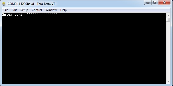
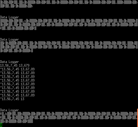
   I am using the Launchpad to read serial data from an instrument. Each reading from the instrument is  prefixed with the '~' character. I am trying to read this serial input (via UART5). However, I have some trouble parsing this data. Here is the portion of code I am using:

int b=0;
int noofreadingstoaverage5;
while (b<noofreadingstoaverage){

   //c=UARTCharGetNonBlocking(UART5_BASE);

   c=UARTCharGet(UART5_BASE);

   UARTprintf("%c",c); // echo character

   if ((c=='~')||(c==126)) {
      b++;
      UARTprintf("\n%i",b);
   }

}


The trouble is the input '~' is not being counted. So b remains 0. How do I fix this?

Thanks.

Mike

  • A few questions

      I presume comparing both to ~ and 126 is a leftover test?  Including both is at best confusing for later maintenance.

      How do you know you are actually receiving a ~? I know some serial programs can get in a mode where they only send on newline (allows local line editing).  Depending on how you get the input to the serial port it could be line based.  If you have a local echo then having the character show on the screen is not an absolute guarantee it has been sent.

     Robert

  • Robert,

       I am simulating the instrument's output with an arduino, so I know that '~' is being sent. Here is my arduino code:

    Serial.print("~13,56.7,45 13,67,89");   Serial.write(13);
    Serial1.print("~13,56.7,45 13,67,89"); Serial1.write(13);

     Serial1 is connected to the launchpad. Serial is connected to my desktop, so I can check what exactly is being sent.

    Mike.

  • Mike

    If I read your post correctly, the UARTprintf("%c",c) prints the character but the if statement does not count. Please correct me if I am wrong in anyway.

    Amit

  • Mike Launch said:

    Robert,

       I am simulating the instrument's output with an arduino, so I know that '~' is being sent. Here is my arduino code:

    Serial.print("~13,56.7,45 13,67,89");   Serial.write(13);
    Serial1.print("~13,56.7,45 13,67,89"); Serial1.write(13);

     Serial1 is connected to the launchpad. Serial is connected to my desktop, so I can check what exactly is being sent.

    Mike.


    OK, now how do you know it is being received?


    Robert

  • You note that the apparent reception/processing of, "~" is uncertain - but not that many/most more, "normal/customary" serial characters (i.e. those easily displayed) can be received - and indeed properly increment your counter.

    Would not the inclusion of such data be helpful?  It really is not so stated.  (especially w/clarity & force)

    As posted - we cannot tell if the issue is strictly, "character defined" or a more general serial processing issue.  As some say here (I'm told)  "devil often w/in such detail..."    And that's missing...  (by you & others...)

  • Robert:

       I know that is is being received because SOME of the sent data is printed correctly.  

    Cb1_mobile:

       Unfortunately, I have to include '~' since that is the data being sent by the instrument over which I have no control.=

    Amit:

       Sorry to have not said this. Some of the char are printed. '~' is not.

  • OK, so ~ is not being received, the counter does not matter.

    That leads to the following questions

      Is ~ consistently not received?

      Are other characters not received?  If not, which ones?

    Finally if ~ is indeed consistently not received, what happens when you send a stream of ~?  Do you get a different character or nothing?


    Robert

  • Another good probe character is U (uppercase U).


    Robert

  • Another thing to consider is that "UARTprintf("%c",c)" may block for a long enough time that "UARTCharGet(UART5_BASE)" will not read the next character in time. You should check if the UART driver uses FIFOs and whether any blocking occurs on transmit and receive. What is the baud rate of UART5 and the console? If the console is a lot slower that UART5, it just makes things worse. A way to debug this is to save all the characters in buffer, then examine the buffer after the test.

  • Hi Mike,

      This works below.

      Code from uart_echo


    void
    UARTIntHandler(void)
    {
        unsigned long ulStatus;
    	  unsigned long c;
    
        //
        // Get the interrrupt status.
        //
        ulStatus = UARTIntStatus(UART0_BASE, true);
    
        //
        // Clear the asserted interrupts.
        //
        UARTIntClear(UART0_BASE, ulStatus);
    
        //
        // Loop while there are characters in the receive FIFO.
        //
        while(UARTCharsAvail(UART0_BASE))
        {
            //
            // Read the next character from the UART and write it back to the UART.
            //
            
    			   c = UARTCharGetNonBlocking (UART0_BASE); // added to uart echo
    			   if (c == '`')
    				 {	 
    			     UARTCharPutNonBlocking(UART0_BASE, c); // added to uart echo
    				 } 
    				 
        }
    }

    Output at Terra Term

      -kel

  • Hi Mike,

    Can you probe the UART5 RX Line to see if the "~" indeed is coming on the line. Secondly, what is the configuration of UART5, may be a dump of registers can tell us if there is some configuration subtlety.

    Amit

  • Hello All,

       Thanks for all the suggestions. I tried to gather all the data to a buffer (and hence eliminating any delay that may be caused). My laptop runs a Matlab code that spits out serial data. I know that this is ok, because I connected the laptop to desktop and I can see the correct data send out from the laptop. Next, the RS232 is connected to PE4 and PE5 pins (after converting RS232 to 3.3 V signals with a MAX232 chip).

    b=0;bufferpos=0;
    static char buffer[200] = "";
    
    while (bufferpos<200){
    	if (ROM_UARTCharsAvail(UART5_BASE)) buffer[bufferpos++]=ROM_UARTCharGet(UART5_BASE);
    }
    UARTprintf("Done reading %i chars\n...",bufferpos);
    UARTprintf("\n%s\n",buffer);

    This code also has trouble. Sometimes I see gibberish on the screen like this:

    Making measurements....
    Done reading 200 chars
    ...
    ▒))▒Q▒▒▒▒ ▒ݹŁ▒▒▒▒r▒▒▒▒▒▒
    

    and sometime I get the right result:

    Making measurements....
    Done reading 200 chars
    ...
    
    ~13,56.7,45 13,67,89
    ~13,56.7,45 13,67,89
    ~13,56.7,45 13,67,89
    ~13,56.7,45 13,67,89
    ...
    ...

    I do not know what is causing it to fail. 

    Relevant part of my makefile are:

    PART=TM4C123GH6PGE
    ROOT=/home/launchpad/stellarisware
    
    include ${ROOT}/makedefs
    
    VPATH=${ROOT}/drivers
    VPATH+=${ROOT}/utils
    VPATH+=${ROOT}/third_party/fatfs/src/option
    VPATH+=${ROOT}/third_party/fatfs/port
    VPATH+=${ROOT}/third_party/fatfs/src
    
    
    IPATH=..
    IPATH+=${ROOT}
    IPATH+=${ROOT}/driverlib
    IPATH+=${ROOT}/third_party
    
    
    all: ${COMPILER}
    all: ${COMPILER}/main.axf
    
    ${COMPILER}/main.axf: ${COMPILER}/main.o
    ${COMPILER}/main.axf: ${COMPILER}/uartstdio.o
    ${COMPILER}/main.axf: ${COMPILER}/ustdlib.o
    ${COMPILER}/main.axf: main.ld
    SCATTERgcc_main=main.ld
    ENTRY_main=ResetISR
    
    CFLAGSgcc=-DTARGET_IS_BLIZZARD_RB1
    
    ifneq (${MAKECMDGOALS},clean)
    -include ${wildcard ${COMPILER}/*.d} __dummy__
    endif

  • Hi Mike

    Can you send the UART Configuration that is being done, would want to make sure that Clock Settings and Baud Settings are correct when the gibberish data comes and when the correct data is recieved? Also what is the System Clock that you are using in the TM4C part?

    Amit

  • Amit,

      Here are the settings:

    ROM_FPUEnable();
    ROM_FPUStackingEnable();
    ROM_SysCtlClockSet(SYSCTL_SYSDIV_4 | SYSCTL_USE_PLL | SYSCTL_OSC_MAIN |SYSCTL_XTAL_16MHZ);
    
    
    // --- UART 0  ---
    ROM_SysCtlPeripheralEnable(SYSCTL_PERIPH_GPIOA); 
    ROM_SysCtlPeripheralEnable(SYSCTL_PERIPH_UART0); // Enable UART0
    ROM_GPIOPinConfigure(GPIO_PA0_U0RX);
    ROM_GPIOPinConfigure(GPIO_PA1_U0TX);
    ROM_GPIOPinTypeUART(GPIO_PORTA_BASE, GPIO_PIN_0 | GPIO_PIN_1);
    UARTClockSourceSet(UART0_BASE, UART_CLOCK_PIOSC);
    UARTStdioConfig(0, 115200, 16000000);
    UARTStdioConfig(0, 115200, 16000000);
    
    
    // --- UART 5  ---
    ROM_SysCtlPeripheralEnable(SYSCTL_PERIPH_UART5);
    ROM_SysCtlPeripheralEnable(SYSCTL_PERIPH_GPIOE);
    ROM_GPIOPinConfigure(GPIO_PE4_U5RX);
    ROM_GPIOPinConfigure(GPIO_PE5_U5TX);
    ROM_GPIOPinTypeUART(GPIO_PORTE_BASE, GPIO_PIN_4|GPIO_PIN_5);
    UARTConfigSetExpClk(UART5_BASE, SysCtlClockGet(), 19200 , UART_CONFIG_WLEN_8 | UART_CONFIG_STOP_ONE | UART_CONFIG_PAR_NONE);
    

  • Hi Mike,

    I may have to try the settings on my side as well. A suggestion here would be change the UART-5 Configuration as follows instead of using the System Clock for UART-5 and share the results.

    ROM_GPIOPinTypeUART(GPIO_PORTE_BASE, GPIO_PIN_4|GPIO_PIN_5);

    UARTClockSourceSet(UART5_BASE, UART_CLOCK_PIOSC);

    UARTConfigSetExpClk(UART5_BASE, 16000000, 19200 , UART_CONFIG_WLEN_8 | UART_CONFIG_STOP_ONE | UART_CONFIG_PAR_NONE);

    Amit

  • I would do two things.

    1. Measure your actual baud rate.  Send out 0xAA or 0x55 in a continuous stream and measure the bit width on a  'scope.  If it is a storage 'scope then you should get a pretty good indication of the variance in timing as well.
    2. Lower the baud rate (at least to 9600).  That gets you down to more standard baud rates (yes, I know PCs have supported 115kBaud for some time but there has been more than a few iffy implementations and USB/serial dongles have not been immune)

    Robert

  • No luck with your suggested UART config, Amit. 

    Still the same problem. Sometimes the output is gibberish and sometimes it works.

  • Hi Mike,

         Can you try first using UART0, if you are able to parse "~". This would identify if your RS232 circuitry may be causing your problem.

          I posted earlier that I was able to catch "~". I did that with a Stellaris kit and using uart_echo project as base.

    -kel

  • Kel,

      I got that sorted as I posted in my previous post. I am reading vales into a buffer and then parsing it out. The problem now is that the input read is garbled at time. Just resetting the launchpad  repeatedly seems to fix it at times.

    bufferpos=0;
    while (bufferpos<buffertoread) if (ROM_UARTCharsAvail(UART5_BASE)) buffer[bufferpos++]=ROM_UARTCharGet(UART5_BASE);
    
    for (loop=0;loop<buffertoread;loop++) {
       if (buffer[loop]==126) b++;
    }
    
    
    UARTprintf("Done reading %i chars and read %i values...\n",bufferpos,b);


    Done reading 200 chars and read 0 values...
    ▒)▒Q▒▒▒嵁▒ݹŁŢ▒▒r▒▒▒▒▒


      So I kept resetting it, and then got data that was right. I am completely perplexed. 

  • I got that sorted as I posted in my previous post. I am reading vales into a buffer and then parsing it out. The problem now is that the input read is garbled at time. Just resetting the launchpad  repeatedly seems to fix it at times.

    I suspect that you are troubleshooting the wrong problem. I have done a fair bit of work with the serial port on the launchpad. I presume that you are using interrupts??? Without seeing the entire program chain that does the reading it will not be possible for anybody to do anything but guess.

    To see the problem and top diagnose and solve it I had to insert routines that flipped I/O lines so I could see what routines were being run and when. It was easy to "overrun" the async serial communications.

    Maybe you have to consider using "handshaking" -- but without knowing what your code is -- how would we know?

    Cheers

  • Thanks Dave. I did not want to bother the community members too much so I did not post the entire code. Since I cannot solve it myself, I will post the main code now. The idea is that when you press the left button, the serial data is read, processed and stored. The serial read is in the MakeMeasurements function (line 176 onwards in code below).

    #include <stdint.h>
    #include <stdbool.h>
    #include <math.h>
    #include <time.h>
    #include <string.h>
    #include "inc/hw_types.h"
    #include "inc/hw_memmap.h"
    #include "inc/hw_hibernate.h"
    #include "driverlib/fpu.h"
    #include "driverlib/gpio.h"
    #include "driverlib/hibernate.h"
    #include "driverlib/interrupt.h"
    #include "driverlib/pin_map.h"
    #include "driverlib/rom.h"
    #include "driverlib/sysctl.h"
    #include "driverlib/systick.h"
    #include "driverlib/uart.h"
    #include "utils/uartstdio.h"
    #include "utils/cmdline.h"
    #include "drivers/rgb.h"
    #include "drivers/buttons.h"
    #include "utils/ustdlib.h"
    
    #define APP_BUTTON_POLL_DIVIDER	20
    #define DOSECALUART GPIO_PORTE_BASE
    
    #define buffertoread 200
    
    void ConfigureUART(void);
    
    void AppButtonHandler(void);
    void MakeMeasurements(int noofreadings,int steps,int delaybetweenreadings,int noofreadingstoaverage);
    
    #include "sdcardfunction.h"
    #include "stepper.h"
    
    unsigned int ulButtons;
    unsigned int filenumber=0;
    
    //-------------------------------------------
    //     Interrupt Handler
    //-------------------------------------------
    void SysTickHandler(void) {
    	ulButtons = ButtonsPoll(0,0);
    	AppButtonHandler();
    }
    
    //-------------------------------------------
    //     Main Function
    //-------------------------------------------
    int main(void) {
    
    	FRESULT iFResult;
    
    	ROM_FPUEnable();
    	ROM_FPUStackingEnable();
    	//ROM_FPULazyStackingEnable(); //Enable lazy stacking for interrupt handlers.
    	ROM_SysCtlClockSet(SYSCTL_SYSDIV_4 | SYSCTL_USE_PLL | SYSCTL_OSC_MAIN |SYSCTL_XTAL_16MHZ); // Set the system clock to run at 50MHz from the PLL.
    
    	ROM_SysCtlPeripheralEnable(SYSCTL_PERIPH_SSI0); // Enable the peripherals for SD card
    
    	ButtonsInit();
    	initialisesteppermotor();
    	ConfigureUART(); // Initialize the UART as a console for text I/O.
    
    	// Configure SysTick for a 100Hz interrupt.  The FatFs driver wants a 10 ms tick.
    	ROM_SysTickPeriodSet(ROM_SysCtlClockGet() / 100);
    	ROM_SysTickEnable();
    	ROM_SysTickIntEnable();
    
    	ROM_IntMasterEnable(); // Enable Interrupts 
    
    	UARTprintf("\n\nData Logger\n");
    
    	while(1){
    		SysCtlDelay(delayvalue0);
    	}
    
    	// Mount the file system , using logical disk 0.
    	iFResult = f_mount(0, &g_sFatFs);
    	if(iFResult != FR_OK) { UARTprintf("f_mount error: %i\n", iFResult); return(1); } else { UARTprintf("\nMounted SD card\n");}
    
    	Cmd_ls("/"); // list files in root directory
    
    	iFResult = f_open(&g_sFileObject,"data.txt", FA_CREATE_ALWAYS|FA_WRITE);
    	if(iFResult != FR_OK) { UARTprintf("Error creating file data.txt: %i\n", iFResult); return(1); } else { UARTprintf("\nCreated file data.txt\n");}
    
    
    	int a=0;
    	unsigned int b; 
    	static char buffer[100] = "";
    	while (a<10){
    		usprintf(buffer,"step =%i\n",a++);
    		iFResult = f_write(&g_sFileObject,buffer,strlen(buffer),&b);
    		if(iFResult != FR_OK) { UARTprintf("Error writing to data.txt: %i\n", iFResult); return(1); } 
    		else { UARTprintf("Wrote %i words to data.txt: %i\n", b); }
    	}
    
    	f_close(&g_sFileObject);
    
    	Cmd_ls("/a"); // list files in root directory 
    
    	// Stepper motor 
    	forward(50);
    	backward(10);
    
    	// Unregister a work area before discard it
    	f_mount(0, NULL);
    }
    
    
    //-------------------------------------------
    //     Configure the USB-SERIAL port 
    //-------------------------------------------
    void ConfigureUART(void) {
    
    
    	// --- UART 0  ---
    	ROM_SysCtlPeripheralEnable(SYSCTL_PERIPH_GPIOA); // Enable the GPIO Peripheral used by the UART.
    	ROM_SysCtlPeripheralEnable(SYSCTL_PERIPH_UART0); // Enable UART0
    	ROM_GPIOPinConfigure(GPIO_PA0_U0RX);
    	ROM_GPIOPinConfigure(GPIO_PA1_U0TX);
    	ROM_GPIOPinTypeUART(GPIO_PORTA_BASE, GPIO_PIN_0 | GPIO_PIN_1);
    	UARTClockSourceSet(UART0_BASE, UART_CLOCK_PIOSC); // Use the internal 16MHz oscillator as the UART clock source.
    	UARTStdioConfig(0, 115200, 16000000); // Initialize the UART for console I/O.
    	UARTStdioConfig(0, 115200, 16000000);
    
    
    	// --- UART 5  ---
    	ROM_SysCtlPeripheralEnable(SYSCTL_PERIPH_GPIOE);
    	ROM_SysCtlPeripheralEnable(SYSCTL_PERIPH_UART5);
    	ROM_GPIOPinConfigure(GPIO_PE4_U5RX);
    	ROM_GPIOPinConfigure(GPIO_PE5_U5TX);
    	ROM_GPIOPinTypeUART(DOSECALUART, GPIO_PIN_4|GPIO_PIN_5);
    	ROM_UARTClockSourceSet(DOSECALUART, UART_CLOCK_PIOSC);
    	ROM_UARTConfigSetExpClk(UART5_BASE,ROM_SysCtlClockGet(),19200,(UART_CONFIG_WLEN_8|UART_CONFIG_STOP_ONE|UART_CONFIG_PAR_NONE));
    }
    
    //--------------------------------------------------------------------------
    void AppButtonHandler(void)
    {
    	static unsigned long ulTickCounter;
    	ulTickCounter++;
    
    	switch(ulButtons & ALL_BUTTONS)
    	{
    		case LEFT_BUTTON:
    			if((ulTickCounter % APP_BUTTON_POLL_DIVIDER) == 0){
    				UARTprintf("\n\nMaking measurements....\n");
    				//serialprint(UART5_BASE,"Lowering Pointsource ..."); UARTCharPut(UART5_BASE, 10); 
    				//MakeMeasurements(int noofreadings,int steps,int delaybetweenreadings,int noofreadingstoaverage);
    				//MakeMeasurements(10,510,1,10);
    				MakeMeasurements(1,10,1,5);
    				//backward(10);
    
    			}
    			break;
    		case RIGHT_BUTTON:
    			if((ulTickCounter % APP_BUTTON_POLL_DIVIDER) == 0){
    				UARTprintf("\n\nLowering point source...\n");
    				//serialprint(UART5_BASE,"Reading from EEPROM"); UARTCharPut(UART5_BASE, 10); 
    				UARTCharPut(UART5_BASE, 'r'); UARTCharPut(UART5_BASE, 'e'); UARTCharPut(UART5_BASE, 's');
    				forward(10);
    			}
    			break;
    		case ALL_BUTTONS:
    			break;
    		default:
    			ulTickCounter = APP_BUTTON_POLL_DIVIDER - 1; // reset the tick counter when no buttons are pressed
    			break;
    	}
    }
    
    
    //--------------------------------------------------------------------------
    void MakeMeasurements(int noofreadings,int steps,int delaybetweenreadings, int noofreadingstoaverage){
    
    	// Disable Interrupts. In sequence: A,B,C,D,E,F
    	ROM_IntDisable(16); ROM_IntDisable(17); ROM_IntDisable(18); ROM_IntDisable(19); ROM_IntDisable(20); ROM_IntDisable(46);
    
    	float readings;
    	char c;
    	int b=0,loop;
    	static char buffer[buffertoread] = "";
    
    	ROM_UARTConfigSetExpClk(UART5_BASE,SysCtlClockGet(),19200,UART_CONFIG_WLEN_8|UART_CONFIG_STOP_ONE|UART_CONFIG_PAR_NONE);
    
    	// Turn dose calibrator data streaming on 
    	UARTCharPut(UART5_BASE, 'D'); UARTCharPut(UART5_BASE, 'S'); UARTCharPut(UART5_BASE, '1');UARTCharPut(UART5_BASE, 13);
    	SysCtlDelay(SysCtlClockGet()); // Wait for a second 
    
    	int position=0,bufferpos=0;
    
    	char *token;
    
    	for (position=0;position < noofreadings; position++){
    
    		// Take readings
    		b=0;
    
    		//while (b<noofreadingstoaverage){
    
    			// read data to buffer
    			bufferpos=0;
    			while (bufferpos<buffertoread) 
    				if (ROM_UARTCharsAvail(UART5_BASE)) buffer[bufferpos++]=ROM_UARTCharGet(UART5_BASE);
    
    			
    			token= strtok (buffer,"~");
    			while ( token != NULL){
    				UARTprintf("%s\n",token);
    				token= strtok (NULL,"~");
    				if (token[0]=='~') b++;
    			}
    			UARTprintf("Done reading %i chars and read %i values...\n",bufferpos,b);
    
    			// Start parsing the buffer 
    			//for (loop=0;loop<buffertoread;loop++) {
    			//	if (buffer[loop]==126) b++;
    			//if (b>=noofreadingstoaverage) break;
    			//}
    		//}
    
    		UARTprintf("Done reading %i chars and read %i values...\n",bufferpos,b);
    		UARTprintf("%s\n",buffer);
    
    		//readings=readings/noofreadingstoaverage;
    		//SysCtlDelay(delaybetweenreadings*SysCtlClockGet()/3); // SysCtlDelay take CPU cycles as argument. 
    		//3 loops per CPU cycles
    
    		// move the point source
    		backward(steps);
    
    	} // end for loop for position
    
    	if (b==0) UARTprintf("\n\nSerial Data not avaliable\n"); else UARTprintf("\n\nMeasurements Done...\n");
    
    	// Turn dose calibrator data streaming on 
    	UARTCharPut(UART5_BASE, 'D'); UARTCharPut(UART5_BASE, 'S'); UARTCharPut(UART5_BASE, '0');UARTCharPut(UART5_BASE, 13);
    	SysCtlDelay(SysCtlClockGet()/3); // Wait for a second
    	
    	// Enable Interrupts. In sequence: A,B,C,D,E,F
    	ROM_IntEnable(16); ROM_IntEnable(17); ROM_IntEnable(18); ROM_IntEnable(19); ROM_IntEnable(20); ROM_IntEnable(46);
    
    }
    

    and the simulated output to the launchpad  from my desktop via a python script:

    #!/usr/bin/python
    
    import serial 
    serialport='/dev/ttyUSB0'
    #serialport='/dev/ttyS0'
    ser = serial.Serial(port=serialport,baudrate=19200,bytesize=serial.EIGHTBITS,parity=serial.PARITY_NONE,stopbits=serial.STOPBITS_ONE)
    ser.close()
    ser.open()
    print ser.portstr
    
    a=1
    
    while a:
    	ser.write("~13,56.7,45 13,67,89\n") 
    ser.close()

  • Hi,

    Mike Launch said:
    ROM_UARTClockSourceSet(DOSECALUART, UART_CLOCK_PIOSC);

    I don't think using "DOSECALUART" is correct. You defined DOSECALUART as below.

    Mike Launch said:
    #define DOSECALUART GPIO_PORTE_BASE

    Try this code line instead

    ROM_UARTClockSourceSet(UART5_BASE, UART_CLOCK_PIOSC);

    Have you tried uart_echo as UART5, just to confirm you don't have problems with your UART5 rs232 circuitry.

    -kel

  • Hi Markel,

    I had suggested the same change earlier and that did not help either.

    Amit

  • Hi,

    @Mike, reading your code snippet, there are some problems:
    - you have the SysTicKHandler interrupt at 10 ms. However, inside this interrupt you call MakeMeasurements() function and inside this you have a long 1 sec delay, while some other interrupts are disabled. Not checked if these are UARTs interrupts - anyway this is not a good practice (this can be the reason for repeated resets - only works once…) - you should prioritize your interrupts so none of them should be disabled, and keep the SysTick interrupt working at specified time interval. Using UARTPrintf inside interrupts is also bad practice, since this function is still big enough and you did not profiled this.
    - for UARTs it is not clear why you use two different interfaces and how these are correlated in some way. 
    - seems to use a file system - not sure if it is for sd_card or USB stick - but if it is for sd_card, take into account this also uses its own SysTick handler at 10 ms. Check for USB…
    - also for UARTs: you are not forced to use UARTPrintf, you may avoid this. 
    So your applications needs some major updates/modifications.
    This is usual practice, if some thing does not works perfectly, analyze, think, erase and re-write. This is usual software development cycle, we all step through… Keep in mind the embedded developer's work is a continuous fight with the forth dimension(micro controller's time).
    Petrei
  • Petrei,

      Thanks for your input. As you can judge from my code, I am rather new to this kind of work, and got started by looking at the TI example code. 

    - I set the interrupts so that I can use the buttons to make measurements. The idea was using the right / left buttons to start/stop the measurements. I was trying to combine sd_card and the qs-rgb examples.

    - I use two UARTs because I wanted to read data from the instrument (via UART5) and echo it back on UART0 so that I can check if things are going well.

    - The file system is for a SD-Card. I wanted to read serial data, process it and log it to the SD card. As you may have found out, my example was for a data logger.

    - Could you advice on how I should handle the SysTick handler if I want to use the SD card? I copied it directly from the SD card example.

    Mike

  • How much of this have you had working?

    If you have not had the serial I/O working (reading, echoing and parsing) then you need to separate it out from the other code and get it working separately.  Reduce the number of possible interactions to the minimum.

    Similarly for the SD card.

    Once they both work then and only then can you attempt to make them work together. Even better start going down the test driven development route.

    You will want to avoid doing any 'disk I/O' or any heavy processing in your serial interrupt routines.  Limit yourself to buffering.  Perhaps simple parsing but I'd leave that to processes outside the interrupt routine to give you more flexibility in error detection and recovery.

    Robert

  • I have all the three separate parts working:

    1) using UART.

    2) using SD card.

    3) using the stepper motor driver.

    Combining all the parts together (which was the code I posted) is the problem. In the combined script, the stepper motor and the sd-card both work. It is the serial interface that is the problem. Sometimes it works, sometimes it reads gibberish from the instrument.

  • OK looking at your code, I noticed the same thing Petrei did.

    You are trying to run this from the systick interrupt.  You simply cannot do that.

    You could get away with debouncing the buttons in systick.  Given what you have in the way of a program the control of the sampling should probably be done in main.  Something like

    main()

    {

    /* Init code */

    /* Wait for button */

    /* While not stop button */

              /* Gather data to buffer -- The actual serial I/O can be polled or interrupt driven */

             /* if buffer full */

                    /* Write buffer to disk */

              /* end while */

    /* Write partial buffer to disk */

    }

    There is room for improvement, especially dealing with write times interrupting sample gathering.  But deal with that only when you get the basics working.  (basically you trigger the sampling off of a timer and buffer the readings during the write.  Assuming the SD routines do not disable interrupts)


    Robert


  • Note that this also results in a cleaner program in the sense that the data gathering and logging are separated responsibilities.  No longer interleaved with one another.

    Robert

  • Thanks Robert and Petrei.

    I tried to remove as much code as possible and just test the UART. I am embarrassed to admit that I still have no clue how to read the serial data. I would appreciate any help on how to fix this. Here is the simplified code:

    void SysTickHandler(void) { }
    
    int main(void) {
    
    	// --- UART 0  ---
    	ROM_SysCtlPeripheralEnable(SYSCTL_PERIPH_GPIOA); // Enable the GPIO Peripheral used by the UART.
    	ROM_SysCtlPeripheralEnable(SYSCTL_PERIPH_UART0); // Enable UART0
    	ROM_GPIOPinConfigure(GPIO_PA0_U0RX);
    	ROM_GPIOPinConfigure(GPIO_PA1_U0TX);
    	ROM_GPIOPinTypeUART(GPIO_PORTA_BASE, GPIO_PIN_0 | GPIO_PIN_1);
    	UARTClockSourceSet(UART0_BASE, UART_CLOCK_PIOSC); // Use the internal 16MHz oscillator as the UART clock source.
    	UARTStdioConfig(0, 115200, 16000000); // Initialize the UART for console I/O.
    	UARTStdioConfig(0, 115200, 16000000);
    
    	// --- UART 5  ---
    	ROM_SysCtlPeripheralEnable(SYSCTL_PERIPH_GPIOE);
    	ROM_SysCtlPeripheralEnable(SYSCTL_PERIPH_UART5);
    	ROM_GPIOPinConfigure(GPIO_PE4_U5RX);
    	ROM_GPIOPinConfigure(GPIO_PE5_U5TX);
    	ROM_GPIOPinTypeUART(GPIO_PORTE_BASE, GPIO_PIN_4|GPIO_PIN_5);
    	ROM_UARTClockSourceSet(UART5_BASE, UART_CLOCK_PIOSC);
    	ROM_UARTConfigSetExpClk(UART5_BASE,ROM_SysCtlClockGet(),19200,(UART_CONFIG_WLEN_8|UART_CONFIG_STOP_ONE|UART_CONFIG_PAR_NONE));
    	
    	ROM_FPUEnable();
    	ROM_FPUStackingEnable();
    	ROM_SysCtlClockSet(SYSCTL_SYSDIV_4 | SYSCTL_USE_PLL | SYSCTL_OSC_MAIN |SYSCTL_XTAL_16MHZ);
    	ROM_SysCtlPeripheralEnable(SYSCTL_PERIPH_SSI0);
    	ROM_SysTickPeriodSet(ROM_SysCtlClockGet() / 100);
    	ROM_SysTickEnable();
    	ROM_SysTickIntEnable();
    	ROM_IntMasterEnable(); // Enable Interrupts 
    
    	UARTprintf("\n\nData Logger\n");
    
    	int bufferpos=0;
    	char buffer[200];
    	while (bufferpos<200)
    			if (ROM_UARTCharsAvail(UART5_BASE)) buffer[bufferpos++]=ROM_UARTCharGet(UART5_BASE);
    	UARTprintf("%s\n",buffer);
    
    	return 0;
    }

    As you can see, resetting the device sometimes reads the correct data.

    The data is simulated by a python script on my desktop. 

  • OK, step back and take baby steps.

    First ignore the device on port 5 (we'll get to it later).  Need to verify that the reporting side works well first.

    Modify the output to just send a continuous stream of packets of simulated data.

    Drop the speed to 9600 baud (PC baud rates could be iffy at 115.2k, 9600 is stable on nearly everything). 

    If it works at 9600, then move back to 115.2k and see if it still works.

    Make sure you do multiple power cycle tests at each baud rate as you did here.

    If this works then you can go on and verify the input side.


    Robert

  • Hello All,

       I tried stepping through all the speeds in the ROM_UARTConfigSetExpClk line. Changing the line from:

    ROM_UARTConfigSetExpClk(UART5_BASE,SysCtlClockGet(),19200,UART_CONFIG_WLEN_8|UART_CONFIG_PAR_NONE | UART_CONFIG_STOP_ONE );

    to 

    ROM_UARTConfigSetExpClk(UART5_BASE,SysCtlClockGet()/3,19200,UART_CONFIG_WLEN_8|UART_CONFIG_PAR_NONE | UART_CONFIG_STOP_ONE );

    makes the UART0 print the values received from UART5 correctly.  SysCtlClockGet()/3 was derived from trial and error.

    Mike

  • Hello Mike,

    It seems that the UART is still configured to use the PIOSC clock. Hence when you set the System Clock to 50MHz by calling the SysCltClockSet function the divide by 3 gets you the correct Baud Rate.

    Amit

  • Amit,

      Can you comment on how I avoid using the PIOSC clock? I am working off the TI examples and that is what I saw.

    Mike.

    ROM_FPUEnable();
    	ROM_FPUStackingEnable();
    	ROM_SysCtlClockSet(SYSCTL_SYSDIV_4 | SYSCTL_USE_PLL | SYSCTL_OSC_MAIN |SYSCTL_XTAL_16MHZ);
    	ROM_SysCtlPeripheralEnable(SYSCTL_PERIPH_SSI0);
    	ROM_SysTickPeriodSet(ROM_SysCtlClockGet() / 100);
    	ROM_SysTickEnable();
    	ROM_SysTickIntEnable();
    	ROM_IntMasterEnable(); // Enable Interrupts 
    
    	// --- UART 0  ---
    	ROM_SysCtlPeripheralEnable(SYSCTL_PERIPH_GPIOA); // Enable the GPIO Peripheral used by the UART.
    	ROM_SysCtlPeripheralEnable(SYSCTL_PERIPH_UART0); // Enable UART0
    	ROM_GPIOPinConfigure(GPIO_PA0_U0RX);
    	ROM_GPIOPinConfigure(GPIO_PA1_U0TX);
    	ROM_GPIOPinTypeUART(GPIO_PORTA_BASE, GPIO_PIN_0 | GPIO_PIN_1);
    	UARTClockSourceSet(UART0_BASE, UART_CLOCK_PIOSC); // Use the internal 16MHz oscillator as the UART clock source.
    	UARTStdioConfig(0, 115200, 16000000); // Initialize the UART for console I/O.
    	UARTStdioConfig(0, 115200, 16000000);
    
    	// --- UART 5  ---
    	ROM_SysCtlPeripheralEnable(SYSCTL_PERIPH_GPIOE);
    	ROM_SysCtlPeripheralEnable(SYSCTL_PERIPH_UART5);
    	ROM_GPIOPinConfigure(GPIO_PE4_U5RX);
    	ROM_GPIOPinConfigure(GPIO_PE5_U5TX);
    	ROM_GPIOPinTypeUART(GPIO_PORTE_BASE, GPIO_PIN_4|GPIO_PIN_5);
    	ROM_UARTClockSourceSet(UART5_BASE, UART_CLOCK_PIOSC);
    	ROM_UARTConfigSetExpClk(UART5_BASE,SysCtlClockGet()/3,19200,UART_CONFIG_WLEN_8|UART_CONFIG_PAR_NONE | UART_CONFIG_STOP_ONE );

  • Hi Mike,

    Replace the

    ROM_UARTClockSourceSet(UART5_BASE, UART_CLOCK_PIOSC);
    with
    ROM_UARTClockSourceSet(UART5_BASE, UART_CLOCK_SYSTEM);
    This will put UART5 to be clocked from SYSTEM. The Same can be applied to UART0 but do change the UARTStdioConfig 3 parameter to return value of SysCtlClockGet
    Amit
  • Amit,
    Thanks for all your help. Is there any advantage between using UART_CLOCK_PIOSC over UART_CLOCK_SYSTEM ?
  • Hi Mike,

    The UART_CLOCK_PIOSC is the PIOSC clock. In the Electrical characteristics -> Clocks -> PIOSC Specification the frequency of this clock can vary max of +/-3% across operating Voltage and Temp. If the variation is acceptable then you can save on the cost of a stable external crystal.

    Amit

  • The question this raises is, why did it ever appear to work?  A few percent difference could give flakiness but a factor of three should have resulted in it always failing.

    Robert

  • Hi Robert,

    The factor of 3 is worst case. If the part is on the bordeline for flakiness, then it may work sometimes and not some other times. Please note that the temperature is the core temperature which may be higher than the ambient and hence the borderline would make it more suspectible.

    Amit

  • @Amit,

    Mike Launch said:
    ROM_UARTConfigSetExpClk(UART5_BASE,SysCtlClockGet()/3,19200,UART_CONFIG_WLEN_8|UART_CONFIG_PAR_NONE | UART_CONFIG_STOP_ONE );

    I figured out, since Mike used SysCtlClockGet() (which gets the system clock 50MHz), at his UARTConfigSetExpClk() from the code above, It is just appropriate to set the UARtClockSourceSet second parameter as UART_CLOCK_SYSTEM.

    I am not entirely convinced that using PIOSC as clock source for UART yields errors. Since, it is clearly mentioned at Tiva Datasheet that you can use PIOSC as UART Baud Clock source.

    -kel

  • Hi Kel,

    Using PIOSC as clock source for UART does not yield errors. It is the fact that the clock frequency can vary between 15.52MHz to 16.48MHz, based on the VT conditions other than the process itself, could lead to incorrect Baud divider programming. The most efficient way is to run the PIOSCAL from time to time to make sure that the PIOSC is centered around 16MHz even if the VT changes.

    Amit

  • Amit Ashara said:

    Hi Robert,

    The factor of 3 is worst case. If the part is on the bordeline for flakiness, then it may work sometimes and not some other times. Please note that the temperature is the core temperature which may be higher than the ambient and hence the borderline would make it more suspectible.

    Amit

    Amit that makes no sense at all to me.  A factor of 3 is worst case for what?

    My concern is that by dividing the clock by three the OP went from a flaky UART to a working UART.  That can never be the case.  A standard UART does not become flaky when its baud rate is off by a factor of three it becomes completely wrong.  Off by 3% it might only be flaky if you are unfortunate, if you are fortunate you will fail.

    Robert

  • Kel,

       I obviously do not know what I am doing, but had a lot of questions answered in this forum. I had earlier used both the PIOSC and the ROM_SysCtlClockGet() clocks as in:

    ROM_UARTClockSourceSet(UART5_BASE, UART_CLOCK_PIOSC);
    ROM_UARTConfigSetExpClk(UART5_BASE,ROM_SysCtlClockGet(),19200,UART_CONFIG_WLEN_8|UART_CONFIG_STOP_ONE|UART_CONFIG_PAR_NONE);

    Changing that to :

    //ROM_UARTClockSourceSet(UART5_BASE, UART_CLOCK_PIOSC);
    ROM_UARTConfigSetExpClk(UART5_BASE,ROM_SysCtlClockGet(),19200,UART_CONFIG_WLEN_8|UART_CONFIG_STOP_ONE|UART_CONFIG_PAR_NONE);
    

    solved the problem.

     Many thanks for all your replies.

  • Mike, it makes sense that that change would make it work. 

    It only makes sense that it would change it from flaky to solid if the main clock speed was the same as the PIOSC speed.

    Robert

  • @ Robert,

    You/I reside the exact same page - this long, meandering series.  (your words/sense near duplicates of my own)

    Devil lurks in the necessary details - poster is admittedly new/inexperienced - the facts themselves & chronology of their (untidy) roll-out caused me to, "flee" this series.

    @ Markel,

    Certain of your points/concerns also win this reporter's vote...  (fwtw)

  • Hi Robert,

    Obviously the "%" got missed. The variation of the PIOSC Clock Frequency from the factory calibrated value is +/-3%

    Amit

  • Amit Ashara said:
    Obviously the "%" got missed.

    Perhaps not!

    Poster's code shows a quite clear, "divide by three!" (SysCtlClockGet())   % is not in this equation.

    As past detailed - the roll-out of facts/data was uneven at best - confounded & delayed issue resolution...

  • Hi, I'm trying to run this example and throws me the following error: Fatal Error # 1965: Can not open source file "sdcardfunction.h"
    Can you help me???? thanks
  • Um, this isn't an example working program to begin with.

    Robert

    Side note: we never did find out about that factor of 3
  • Hello Diego.

    I am not sure if a file called sdcardfunction.h exists in TivaWare

    Regards
    Amit