This thread has been locked.

If you have a related question, please click the "Ask a related question" button in the top right corner. The newly created question will be automatically linked to this question.

ADCHardwareOversampleConfigure with ADC_TRIGGER_TIMER on TM4C129X

Hello.

We are using a TM4C129x custom board sampling from 2 channels of the ADC via uDMA and this is triggered via Timer0. We are sampling at 50 KHz, with no problems.

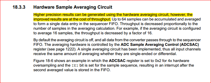
However, don't need such a bandwidth and we would like to use the Hardware Averaging technique explained on the workshop document. 

To do that we have included the line:

  ADCHardwareOversampleConfigure(ADC0_BASE, 4);


But we see no difference on the  time between interruptions or the sampled data. It looks like there is no effect.

Should not be the Tiva device, triggering the  ADC interrupt 4 times later?

Our aim is to get an oversampled 12.5 KHz signal.


Thank you

  • I have read other users/posters with the same issue with Tm4c129x and ADCHardwareOversampleConfigure.


    How could we solve this?

    Thank you.

  • Hi Amit.

    Could you tell us something about this issue?

    Thank you.

  • Hello PAk,

    I am working on it. You should have a response on the code post/trial code in the next couple of days.

    Regards

    Amit

  • Amit Ashara said:

    Hello PAk,

    I am working on it. You should have a response on the code post/trial code in the next couple of days.

    Regards

    Amit

    Hello Amit. 

    Just in case it helps you, here is what we have found:

    • The instruction ADCHardwareOversampleConfigure is not writting the ADC_SAC register. Working OK.
    • If we debug the program and change the ADC_O_SAC register, we only see changes on the averaged signal when the register is set at 32X or 64X.
    • When the register is at 32X or 64X, we get a fixed conversion time for the 512 samples, no matter the sampling frequency.
    • If the conversion time is higher then we get fixed conversion times for 8X and 16X too.

    For example, at 70KHz (which throws a 7.314ms conversion time):

    Oversampling Value

    ConversionTime (512 samples)

    Actual sampling freq (1sample)

    PRE-Averaged Sampling freq (1sample)
    0X 7.314ms 70kHz X
    2X 7.314ms 70kHz X
    4X 7.314ms 70kHz X
    8X 8.190ms 62.515kHz 500.12 MHz
    16X 16.32ms 31.37kHz 501 MHz
    32X 32.77ms 15.62kHz 499.96 MHz
    64X 65.5ms 7.816 kHz 500.27 MHz

    So it seems, that the ADC conversion clock is fixed at 500MHz, and only if the oversampled conversion time is bigger than the timer clock (at 70kHz) it is "working" (at a 500MHz rate).

    We ran another test at 30 KHz getting:

    Oversampling Value

    ConversionTime (512samples)

    Actual sampling freq (1sample) PRE-Averaged Sampling freq (1sample)
    0X 17.066ms 30kHz X
    2X 17.066ms 30kHz X
    4X 17.066ms 30kHz X
    8X 17.066ms 30kHz X
    16X 17.066ms 30kHz X
    32X 32.77ms 15.62kHz 499.96 MHz
    64X 65.5ms 7.816 kHz 500.27 MHz

    Which confirms our thoughts.

    What do we have to do to get the oversampled data from our timer0 clock?

    Regards.

  • Hello PAk,

    I ran the configuration of ADC For Hardware Oversampling and I get the interrupt after 4x time the conversion. What I did was in the Interrupt Routine toggle a GPIO H->L and then before enabling the Sequencer using processor trigger toggled it L-H. So effectively the "H" time is the conversion time.

    Did you check this step and co-relate it to the data

    Regards

    Amit

  • Amit Ashara said:

    I ran the configuration of ADC For Hardware Oversampling and I get the interrupt after 4x time the conversion. What I did was in the Interrupt Routine toggle a GPIO H->L and then before enabling the Sequencer using processor trigger toggled it L-H. So effectively the "H" time is the conversion time.

    Did you check this step and co-relate it to the data

    What setup did you use for your timer?

    Which is your sampling frequency?

    Here is my code for the timer:

    void InitSamplingTimer()
        {
        //
        // Set up timer0A to be a periodic timer at sampling freq.
        //
           
        SysCtlPeripheralEnable(SYSCTL_PERIPH_TIMER0);
        TimerConfigure(TIMER0_BASE, TIMER_CFG_PERIODIC);
        TimerControlTrigger(TIMER0_BASE, TIMER_A, true);
        TimerLoadSet(TIMER0_BASE, TIMER_A, g_ui32SysClock / (g_uiSamplingFreq - 1));
        IntEnable(INT_TIMER0A_TM4C129);
        TimerIntEnable(TIMER0_BASE, TIMER_TIMA_TIMEOUT);
        TimerEnable(TIMER0_BASE, TIMER_A);
        }

    void Timer0AIntHandler(void)
        {
    
        //
        // Clear the timer interrupt.
        //
        TimerIntClear(TIMER0_BASE, TIMER_TIMA_TIMEOUT);
    
        }

    Regards.

  • void Timer0AIntHandler(void)
        {

        //
        // Clear the timer interrupt.
        //
        TimerIntClear(TIMER0_BASE, TIMER_TIMA_TIMEOUT);
        // insert delay here
        }

    Bet you that the insertion of some delay - just post that, "TimerIntClear" will prove useful.  (suspect that you're reentering that interrupt handler - the interrupt may not yet be fully cleared...)

  • cb1- said:

    void Timer0AIntHandler(void)
        {

        //
        // Clear the timer interrupt.
        //
        TimerIntClear(TIMER0_BASE, TIMER_TIMA_TIMEOUT);
        // insert delay here
        }

    Bet you that the insertion of some delay - just post that, "TimerIntClear" will prove useful.  (suspect that you're reentering that interrupt handler - the interrupt may not yet be fully cleared...)

    Thank you for your answer cb1.

    Actually it is a TIMER_CFG_PERIODIC, it shouldn't matter. Anyway will try it.

    Do you recommend any instruction so the processor won't "optimize" it!!

    Amit Ashara said:
    ....in the Interrupt Routine toggle a GPIO H->L and then before enabling the Sequencer using processor trigger toggled it L-H.

    Amit.

    Just realized this from your answer. We are not using processor trigger!!! We are using ADC_TRIGGER_TIMER, triggering the ADC via Timer0 as I said in the first post.

    Besides we are servicing the ADC via uDMA. 

    Regards.

    Added Later:


    Have set a trigger on the Timer0AIntHandler and another on the interrupt from the ADC and the timer values are almost perfect (70KHz for the timer and 7.314msec for the 512 uDMA interrupt)....but not Oversampled data at all.


  • Hello PAk,

    The behavior of ADC is as expected even with a 70KHz Timer Trigger. The UDMA also services the ADC properly. How are you making the measurements?

    Regards

    Amit

  • Amit Ashara said:
    The behavior of ADC is as expected even with a 70KHz Timer Trigger. The UDMA also services the ADC properly. How are you making the measurements?

    I Amit, as you suggested I have set up a GPIO output pin, and I am toggling it inside the ADC interrupt. I am seeing the same behaviour as the tables with the measurements I posted before.

    Don't you see the 500MHz oversampled data?

    I assume we are both using Tivaware 2.1 on a XM4C1294 device rev1 (Launchpad).

    Would you mind to send me your test project so I could check the differences between our sources?

    Thank you.

  • Hello PAk,

    Sure, would send the code post when I am in. However looking at the table there is a critical information that you may have overlooked. When using a 70KHz timer trigger, the trigger is happening at 14.28us. Now you are using two channels with an averaging of 4 which would mean that ~8us would be used up leaving the ADC Controller Idle for ~6.28us. At an averaging of 8 it would exceed the time period between triggers causing the ADC to loss track of the averaging.

    At 30KHz the same time frame is now 33.33us allowing 8 and 16x to work but messes up 32x would again fall in the critical region where a trigger comes earlier than conversion and averaging is complete.

    Regards

    Amit

  • Amit Ashara said:
    Sure, would send the code post when I am in.

    Thank you Amit. I think the code will help.

    Amit Ashara said:
    However looking at the table there is a critical information that you may have overlooked. When using a 70KHz timer trigger, the trigger is happening at 14.28us. Now you are using two channels with an averaging of 4 which would mean that ~8us would be used up leaving the ADC Controller Idle for ~6.28us. At an averaging of 8 it would exceed the time period between triggers causing the ADC to loss track of the averaging.

    That explains a lot!! However, I was cheated (once again) by the marketing team, and I was supposing that ADC conversion rate on 129X was 2MSPS by default.

    But the truth came out when I looked at the datasheet:

    Amit Ashara said:
    At 30KHz the same time frame is now 33.33us allowing 8 and 16x to work but messes up 32x would again fall in the critical region where a trigger comes earlier than conversion and averaging is complete.

    However, this is rising some questions/doubts. When you are setting a timer sampling at 70KHz, and ADC HW averaging is 4, then you are getting an effective sampling rate of 17.5kHZ, right?

    From your calculations, it seems, that what you are getting is a 280kHz frame averaged by 4 at a 70KHz....which is not the same.

    From the datasheet, I think, the throughput has to shrink.

     From the instruction:

    ADCClockConfigGet(ADC0_BASE,&clk_div);

    I know CLKDIV field (from ADCCC register) value is 1. Would a value of 0 set the ADC conversion time at 2MSPS?

    Regards.

  • Hello PAk,

    To use the 2MSPS you would need to change the clock to PLL and then use the correct divider value. As an example if the System Clock from PLL is 120MHz (VCO being 480 MHz) then

    ADCClockConfigSet(ADC0_BASE,ADC_CLOCK_SRC_PLL | ADC_CLOCK_RATE_FULL, 15);

    As for the 2MSPS, it can be used (but is not full characterized which would happen shortly). So Mktg still holds... and data sheet will change.

    The ADC always has a conversion time of 1us per channel. When using HW averaging it takes the HW average number of times x number of channels worth of time to generate the data. This has got nothing to do with trigger rate as that is something the user code has to take into account. Hence in this case the Effective Conversion rate for HW average of 4 and 2 channels is 8us which in turn becomes 125KSPS.

    Regards

    Amit

  • Amit Ashara said:

    To use the 2MSPS you would need to change the clock to PLL and then use the correct divider value. As an example if the System Clock from PLL is 120MHz (VCO being 480 MHz) then

    ADCClockConfigSet(ADC0_BASE,ADC_CLOCK_SRC_PLL | ADC_CLOCK_RATE_FULL, 15);

    Thank you. Will try it.

    Amit Ashara said:
    The ADC always has a conversion time of 1us per channel. When using HW averaging it takes the HW average number of times x number of channels worth of time to generate the data.

    .....

    Hence in this case the Effective Conversion rate for HW average of 4 and 2 channels is 8us which in turn becomes 125KSPS.

    Then, how to be sure that the data is averaged?

    Amit Ashara said:
    This has got nothing to do with trigger rate as that is something the user code has to take into account.

    So, is there a way to get averaged data from a specific trigger rate? i.e., setting a 800ksps rate (via timer) and averaging by 16 to get a 50ksps.


    Or is it better to just stop the timer and reconfigure the trigger rate?


    Thank you.

  • Hello PAk,

    1. The trigger is just for start of conversion. The ADC Block will take care of Starting the conversion for the number of samples for averaging times, average the same and then generate the interrupt. That is guaranteed by design

    2. The effective data rate can be managed by using timer in one shot or using the processor trigger. However what is important to note is if the application requires such a sampling rate or converted data (averaged or non-averaged)

    Regards

    Amit

  • Amit Ashara said:

    1. The trigger is just for start of conversion. The ADC Block will take care of Starting the conversion for the number of samples for averaging times, average the same and then generate the interrupt. That is guaranteed by design

    2. The effective data rate can be managed by using timer in one shot or using the processor trigger. However what is important to note is if the application requires such a sampling rate or converted data (averaged or non-averaged)

    Thank you Amit. All is clear now.

    However, I have a new doubt. I removed the Timer0 interruption (the one that triggers the ADC), since at 800KHz ipnterrupt was a lot for the processor to handle.

    To get track of the conversion rate I set GPIO_PD0_T0CCP0 to ouput the timer signal, and set the timer as PWM (since it is only supported in this mode) by using: 

     TimerConfigure(TIMER0_BASE,  TIMER_CFG_A_PWM | TIMER_CFG_SPLIT_PAIR);

    But if I get the signal on the PD0 pin the ADC interrupt is not triggered and vice versa. So if I set:

    TimerConfigure(TIMER0_BASE, TIMER_CFG_PERIODIC|TIMER_CFG_A_PWM);
    
    or 
    
    TimerConfigure(TIMER0_BASE, TIMER_CFG_SPLIT_PAIR| TIMER_CFG_PERIODIC);
    

    then the ADC interrupt is triggered but I cannot see the timer.

    Is there a way to achieve this?

    Our Timer function now is:

    void InitSamplingTimer()
        {
        //
        // Set up timer0A to be a periodic timer at sampling freq.
        //
           
        SysCtlPeripheralEnable(SYSCTL_PERIPH_TIMER0);
    
        SysCtlPeripheralEnable(SYSCTL_PERIPH_GPIOD);
        GPIOPinConfigure(GPIO_PD0_T0CCP0);
        GPIOPinTypeTimer(GPIO_PORTD_BASE, GPIO_PIN_0);
    
    
        //TimerConfigure(TIMER0_BASE, TIMER_CFG_PERIODIC); -//Now is PWM
        TimerConfigure(TIMER0_BASE, TIMER_CFG_PERIODIC | TIMER_CFG_A_PWM | TIMER_CFG_SPLIT_PAIR);
    
    
        TimerLoadSet(TIMER0_BASE, TIMER_A, (g_ui32SysClock / g_uiSamplingFreq) - 1);
        TimerMatchSet(TIMER0_BASE, TIMER_A, g_ui32SysClock / (g_uiSamplingFreq*2));  //50% duty cycle at init
    
      
        TimerControlTrigger(TIMER0_BASE, TIMER_A, true);
        TimerEnable(TIMER0_BASE, TIMER_A);
        }

  • PAk said:

    To get track of the conversion rate I set GPIO_PD0_T0CCP0 to ouput the timer signal, and set the timer as PWM (since it is only supported in this mode) by using: 

     TimerConfigure(TIMER0_BASE,  TIMER_CFG_A_PWM | TIMER_CFG_SPLIT_PAIR);

    But if I get the signal on the PD0 pin the ADC interrupt is not triggered and vice versa. So if I set:

    TimerConfigure(TIMER0_BASE, TIMER_CFG_PERIODIC|TIMER_CFG_A_PWM);
    
    or 
    
    TimerConfigure(TIMER0_BASE, TIMER_CFG_SPLIT_PAIR| TIMER_CFG_PERIODIC);
    

    then the ADC interrupt is triggered but I cannot see the timer.

    Is there a way to achieve this?

    Finally I did it using both Timers (A and B) on Timer 0.

    Finally I have a last question.

    I have realized that the ADC2IntHandler is triggered in every timer cycle, and if the uDMA count has reached the selected value, then it enters the if (ulMode == UDMA_MODE_STOP) block.

    Is there a way to reduce the number of triggered interrupts without affecting the dma interrupt? I.e. entering the interruption once every four samples (actually it wouldn't matter since we are capturing 1024 samples via uDMA).

    It seems that it is not important, but I have noticed some overhead above 500Ksps rate.

    Thank you.

  • Hello PAk

    On DMA Done Interrupt, the CPU must stop the timer by calling TimerDisable. Once the UDMA is re-initalized then it can re-enable the Timer.

    Regards

    Amit

  • Amit Ashara said:
    On DMA Done Interrupt, the CPU must stop the timer by calling TimerDisable. Once the UDMA is re-initalized then it can re-enable the Timer.

    Thank you Amit, but that is clear, I am talking about the number of interrupts on a ADCInterrupt. Is there a way to only have an interruption every X samples?

  • Hello PAk,

    No, such a capability does not exist. The only way to increase the X sample count is the oversampling.

    Regards

    Amit