This thread has been locked.

If you have a related question, please click the "Ask a related question" button in the top right corner. The newly created question will be automatically linked to this question.

Error connecting to the target Device ID is not recognized or is not supported by driver

Other Parts Discussed in Thread: TM4C1231H6PM, EK-TM4C123GXL, UNIFLASH, LMFLASHPROGRAMMER

I am trying to flash code onto a TM4C1231H6PM on a custom board using the XDS200. The first time I flashed code it did flash but I got some error about breakpoints being out of bounds or something. Unfortunately I did not pay much attention to this. On all subsequent attempts I get the following error:

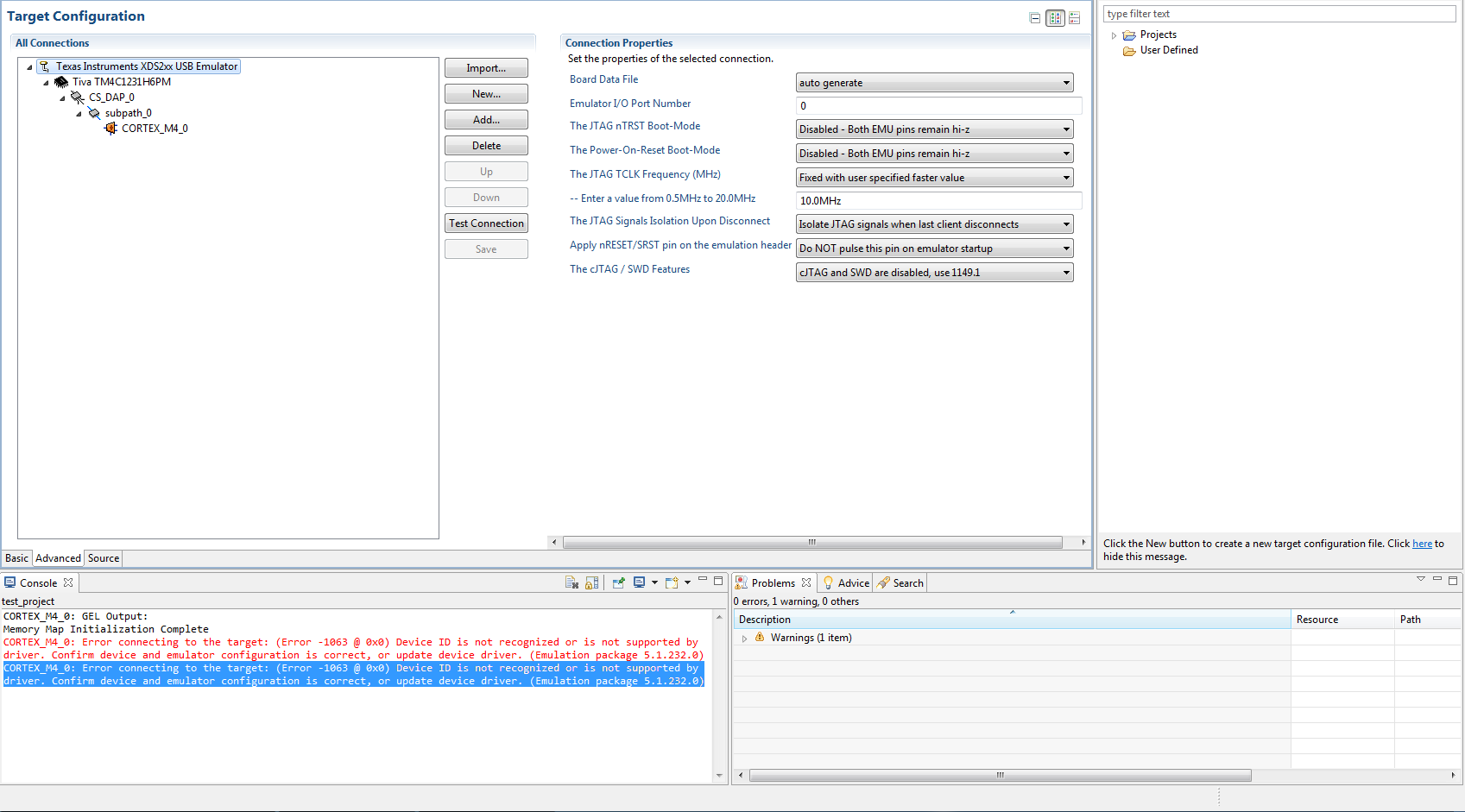
CORTEX_M4_0: Error connecting to the target: (Error -1063 @ 0x0) Device ID is not recognized or is not supported by driver. Confirm device and emulator configuration is correct, or update device driver. (Emulation package 5.1.232.0)

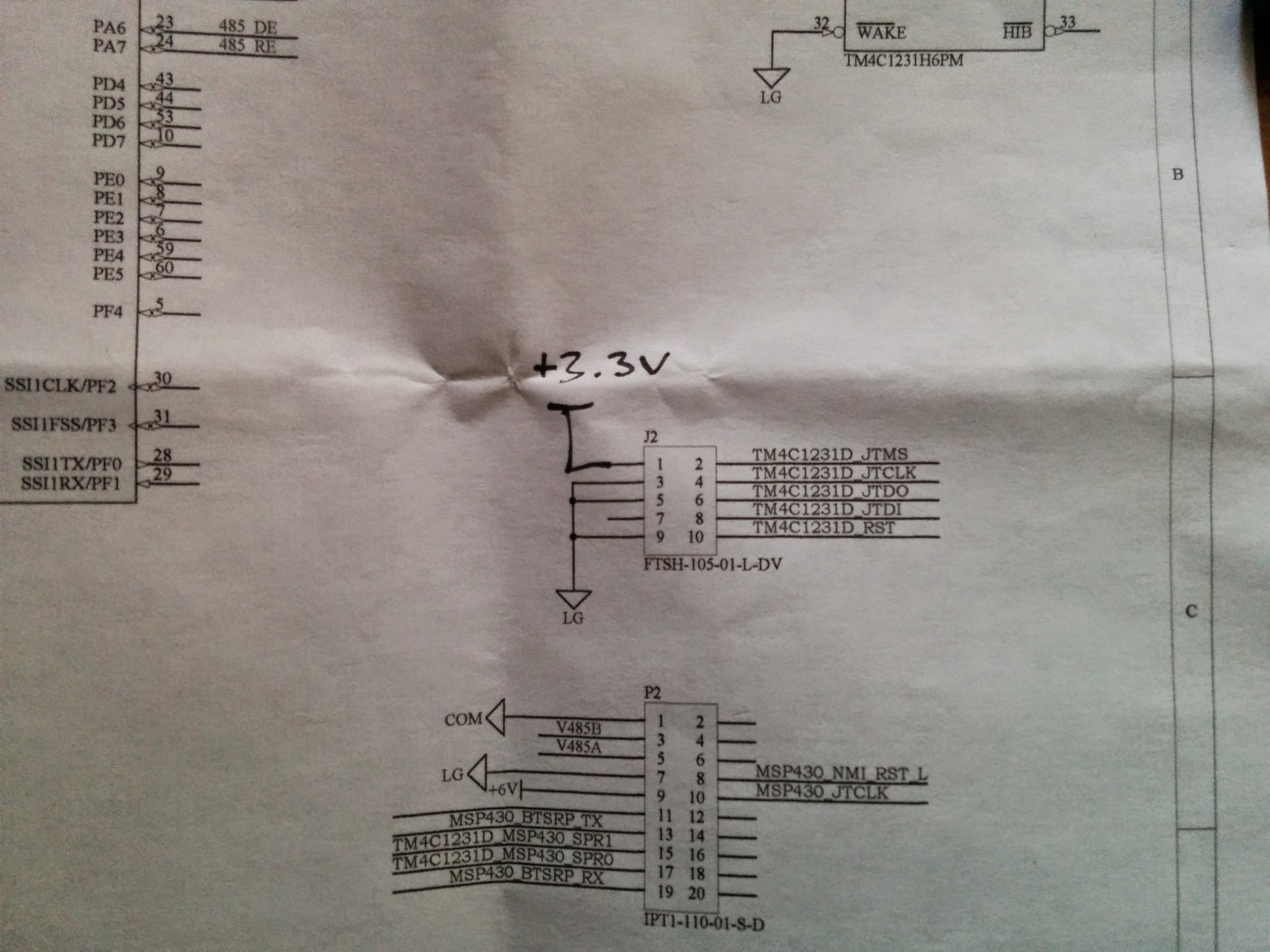
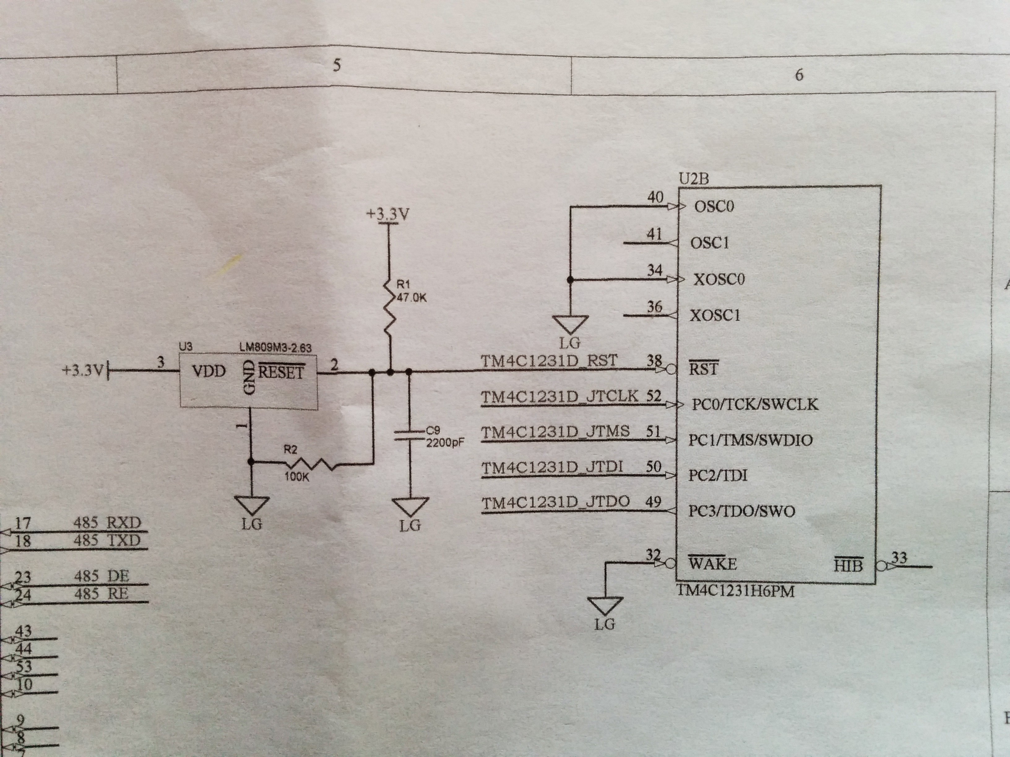
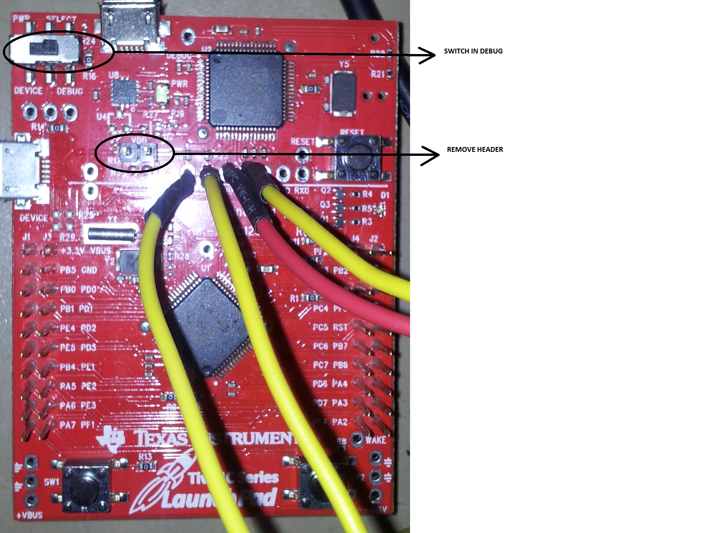
I'm attaching a screenshot of my target configuration and the relevant schematics. Any help is much appreciated!

  • Hello Gabriel,

    Great post: Detail of the relevant schematic of the board, and clear description of the issue, something which we end up in asking our forum members always to give out for basic analysis.

    Coming to the issue, since you were able to flash the code the first time around, could you look into the following things in the code itself

    1. Is the JTAG ports being reconfigured

    2. Is the MOSC being used in the code either as PLL source or system clock source? And how the system clock was being configured

    3. Is EEPROM being used by your code?

    Summary: Code post would be useful as well

    Lastly, do you have a TM4C129 or TM4C123 LaunchPad handy... If we need to run the unlock sequence.

    Regards

    Amit

  • Thanks for your reply Amit. I'll try to provide some better debugging information by addressing your questions below. 

    1. Is the JTAG ports being reconfigured

    I am not reconfiguring the JTAG ports.

    2. Is the MOSC being used in the code either as PLL source or system clock source? And how the system clock was being configured

    This may be an issue. I was mistakenly configuring the system clock to use the main oscillator instead of the internal oscillator with the following code:

    SysCtlClockSet(SYSCTL_SYSDIV_4 | SYSCTL_USE_PLL | SYSCTL_OSC_MAIN | SYSCTL_XTAL_16MHZ);

    I am going to change this code to

    SysCtlClockSet(SYSCTL_SYSDIV_4 | SYSCTL_USE_PLL | SYSCTL_OSC_INT | SYSCTL_XTAL_16MHZ);

    3. Is EEPROM being used by your code?

    My code is not using the EEPROM

    Summary: Code post would be useful as well

    The code is quite a large project consisting of many modules and linking in several custom libraries. That combined with it being proprietary and confidential means that I cannot really post it here unfortunately. I can post snippets of the particular pieces that might be relevant though. I realize this makes it more difficult to help so I apologize for that.

    Lastly, do you have a TM4C129 or TM4C123 LaunchPad handy... If we need to run the unlock sequence.

    I have the EK-TM4C123GXL and the DK-TM4C123G handy. 

  • Hi,

    JTAG pins need pull-up resistors;

    According to the data sheet, the JTAG clock frequency must be lower than 1/8 of starting clock frequency, so maximum allowable shoud be 2MHz instead of 10. A more safe value of 1 MHz would be OK.

    Petrei

  • Hello Gabriel,

    On top of what Petrei has mentioned (Thanks Petrei as that is a vital information), you would need to re-wire the EK-TM4C123 to your custom board (remember that the EK-TM4C123 will now be your debugger to unlock the custom board).

    1. Keep the Switch in Debug Mode

    2. Remove the VDD Header

    3. Connect the JTAG Wires as shown in the center of the board (and the GND has to be common between the two boards)

    Now you can run the JTAG Unlock Sequence from LMFlashProgrammer or UNIFLASH to erase the code that has caused the problem (which has been due to the MOSC being used as the clock source).

    Regards

    Amit

  • Thanks for the advice. I'll update this thread once I get a chance to try out the suggestions.

  • Thanks Amit and Petrei, I followed your advice and am now able to flash and debug code on my custom tm4c1231h6pm boards using the xd200.

    I did not add pull up resistors yet, as this will require a board revision, but things are working for now without them.

    Thanks for the fast response. The support in the E2E community is outstanding.

  • Gabriel Hein said:
    Thanks for the fast response. The support in the E2E community is outstanding.

    Yes, but that depends on how you ask for help. Normally if someone just comes here and say: "this is not working, fix it", normally that kind of post won't get much attention.
    You right in the first post, gave the error message, a screenshot and hardware schematics. It makes it much more appealing to help you.
    Problems can come from bad compiler configuration, hardware or software. And you provided always a good amount of information.

    Good job! That's the best way to get help!


    TI should send a bag of cookies to everyone. 
    If that happened, Amit would have enough cookies to open a really big cookie shop.