This thread has been locked.

If you have a related question, please click the "Ask a related question" button in the top right corner. The newly created question will be automatically linked to this question.

I2C Slave data read problem. Stellaris / Tiva, CC2541.

Other Parts Discussed in Thread: CC2541

Hi,

I have a problem with I2C slave implementation on Stellaris / Tiva. 

Im running CC2541 Keyfob as a I2C Master and LM4F120H5QR as a Slave (TM4C123G in final design - I keep in mind differences like I2C1_SLAVE_BASE -> I2C1_BASE). I am using CCS 6.0.0.00190. Because stellaris will maintain some calculations I am using an interrupt for handle I2C.

My goals are:

1. Receive first byte and depending on it (like register address) select next steps in switch(). 

2. For instance I received 10, so I wanna put one byte I2CSlaveDataPut(I2C1_SLAVE_BASE, someValue), if I received 20 other value and so on.

Thats it! But here comes the problem. 

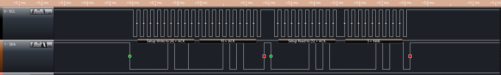
From the LEDS I am using for control occurence of matches I can see that program steps into right cases but the value on the SDA during sending from stellaris is always the same 0x05 as on the picture. It should be the one in case eg 10 but not...

Q1: Why is this happening? 

I have tried adding some whiles with I2CSlaveStatus() but without good results.

Q2: How to catch EXACTLY the first byte (not a WRITE request or something else) and then send data depending on received byte?

Speed doesn't matter. Same results when running 533kHz and 33kHz as a CC2541 Master. There must be my bad. Maybe configuration of the slave module.

And i almost forgot... Q3: How by using I2CSlaveACKOverride and I2CSlaveACKValueSet reject request by put NACK during READ (from stellaris slave) cycle? My attempts failed.

Code: 

#include "inc/hw_memmap.h"
#include "inc/hw_types.h"
#include "inc/hw_ints.h"
#include "inc/hw_i2c.h"
#include "driverlib/debug.h"
#include "driverlib/fpu.h"
#include "driverlib/gpio.h"
#include "driverlib/pin_map.h"
#include "driverlib/rom.h"
#include "driverlib/sysctl.h"
#include "driverlib/i2c.h"
#include "driverlib/interrupt.h"

#ifdef DEBUG
void
__error__(char *pcFilename, uint32_t ui32Line)
{
}
#endif

/* variables, const */

	#define SLAVE_OWN_ADDRESS	0x02

	volatile unsigned short fir = 0;
	unsigned short i = 0;
	unsigned short flag =0;

void I2C1SlaveIntHandler(void)
{
	I2CSlaveIntClear(I2C1_SLAVE_BASE);
	I2CSlaveIntClearEx(I2C1_SLAVE_BASE,I2C_SLAVE_INT_DATA);


	fir = I2CSlaveDataGet(I2C1_SLAVE_BASE);
	switch(fir)
	{
	case 8:
		I2CSlaveDataPut(I2C1_SLAVE_BASE, 8);
		GPIOPinWrite(GPIO_PORTF_BASE,GPIO_PIN_1,GPIO_PIN_1);
		break;
	case 2:
		I2CSlaveDataPut(I2C1_SLAVE_BASE, 2);
		GPIOPinWrite(GPIO_PORTF_BASE,GPIO_PIN_1,GPIO_PIN_1);
		break;
	case 5:
		I2CSlaveDataPut(I2C1_SLAVE_BASE, 0xCA);  //before here was 0x05 - when picture was captured
		//GPIOPinWrite(GPIO_PORTF_BASE,GPIO_PIN_1,GPIO_PIN_1);
		break;
	case 10:
		while(I2CSlaveStatus(I2C1_SLAVE_BASE) & I2C_SLAVE_ACT_TREQ)
				{
				I2CSlaveDataPut(I2C1_SLAVE_BASE, 255);
				}
		GPIOPinWrite(GPIO_PORTF_BASE,GPIO_PIN_3,GPIO_PIN_3);
		break;
	case 20:
		I2CSlaveDataPut(I2C1_SLAVE_BASE, 20);
		break;
	case 30:
		I2CSlaveDataPut(I2C1_SLAVE_BASE, 30);
		break;
	default:
		//I2CSlaveDataPut(I2C1_SLAVE_BASE, 64);

		break;
	}

	GPIOPinWrite(GPIO_PORTF_BASE,GPIO_PIN_2,GPIO_PIN_2);
	flag = 1;
	fir = 0;
}

main(void)
 {
	ROM_FPUEnable();
    ROM_FPULazyStackingEnable();
    SysCtlClockSet(SYSCTL_SYSDIV_4 | SYSCTL_USE_OSC | SYSCTL_OSC_MAIN |
                   SYSCTL_XTAL_16MHZ);
    ROM_SysCtlPeripheralEnable(SYSCTL_PERIPH_GPIOF);
    ROM_SysCtlPeripheralEnable(SYSCTL_PERIPH_GPIOA);
    ROM_GPIOPinTypeGPIOOutput(GPIO_PORTF_BASE, GPIO_PIN_1);
    ROM_GPIOPinTypeGPIOOutput(GPIO_PORTF_BASE, GPIO_PIN_2);
    ROM_GPIOPinTypeGPIOOutput(GPIO_PORTF_BASE, GPIO_PIN_3);

    SysCtlPeripheralEnable(SYSCTL_PERIPH_I2C1);
    ROM_GPIOPinConfigure(GPIO_PA6_I2C1SCL);
    ROM_GPIOPinConfigure(GPIO_PA7_I2C1SDA);
	GPIOPinTypeI2CSCL(GPIO_PORTA_BASE, GPIO_PIN_6);
	GPIOPinTypeI2C(GPIO_PORTA_BASE, GPIO_PIN_7);
    I2CSlaveEnable(I2C1_SLAVE_BASE);
    I2CSlaveInit(I2C1_SLAVE_BASE, SLAVE_OWN_ADDRESS);

    /* Enable interrupts */
    I2CSlaveIntEnable(I2C1_SLAVE_BASE);
    I2CSlaveIntEnableEx(I2C1_SLAVE_BASE, I2C_SLAVE_INT_DATA);
	IntEnable(INT_I2C1);
    IntMasterEnable();

    while(1)
    {
    	if(flag)
    	{
    		flag = 0;
    		GPIOPinWrite(GPIO_PORTF_BASE,GPIO_PIN_1,0);
    		GPIOPinWrite(GPIO_PORTF_BASE,GPIO_PIN_2,0);
    		i++;
    		if(i > 5)
    		{
    			i = 0;
    			GPIOPinWrite(GPIO_PORTF_BASE,GPIO_PIN_3,0);
    		}
    	}
    }
}

PS. I realized that I have added this post on wrong forum -> LM3 so I have deleted it there and post here. Newbie fail :)

Thanks,

Piotr.

  • Hello Piotr,

    The I2C Slave Transmit data will be put out only when a Transmit Request comes. So the code should be done in the manner where based on the RREQ the Interrupt Handler preps a global data buffer and exits the Interrupt loop. If a TREQ comes then it puts the data in the buffer.

    As for Q.2: There is a FBR bit in the I2C Slave Status Register which will tell you if this is the first byte received after address...

    As for the ACK Override, you need to set the bit-0 ACKOEN. On receiving a data byte, you need to then write to the bit-1 ACKOVAL so that I2C Slave can ACK or NACK

    Regards

    Amit

  • Thank you Amit,

    Amit Ashara said:

    The I2C Slave Transmit data will be put out only when a Transmit Request comes. So the code should be done in the manner where based on the RREQ the Interrupt Handler preps a global data buffer and exits the Interrupt loop. If a TREQ comes then it puts the data in the buffer.

    That's it. There are two interrupts, one when Master writes and second when requesting data. Now the code works but not perfect. Usually I receive correct values but sometimes in the case I2C_SLAVE_ACT_RREQ_FBR described below I am receiving the value, that I have sended in case I2C_SLAVE_ACT_TREQ by executing I2CSlaveDataPut() in previous interrupt. Eg when I had sent 50 I am receiving 50 - not the value from master.

    Q1. How to get rid of that? I must wait in interrupt until the specific condition is met? If yes, which one and where?

    case I2C_SLAVE_ACT_RREQ_FBR:
    {
    // here when Master sends exact 1 B - normal write
    receivedCC2541 = I2CSlaveDataGet(I2C1_SLAVE_BASE);
    break;
    }

    Full code:

    #include "inc/hw_memmap.h"
    #include "inc/hw_types.h"
    #include "inc/hw_ints.h"
    #include "inc/hw_i2c.h"
    #include "driverlib/debug.h"
    #include "driverlib/fpu.h"
    #include "driverlib/gpio.h"
    #include "driverlib/pin_map.h"
    #include "driverlib/rom.h"
    #include "driverlib/sysctl.h"
    #include "driverlib/i2c.h"
    #include "driverlib/interrupt.h"
    
    #include "driverlib/uart.h"
    #include "utils/uartstdio.h"
    #include "peripherials.h"
    
    #ifdef DEBUG
    void
    __error__(char *pcFilename, uint32_t ui32Line)
    {
    }
    #endif
    
    /* variables, const */
    
    	#define SLAVE_OWN_ADDRESS	0x02
    
    	typedef
    			volatile unsigned short vus;
    	static vus receivedCC2541;
    	static vus buffor10[2] = {0,10};
    	static vus buffor20[2] = {0,20};
    	static vus buffor30[2] = {0,30};
    	static vus buffor40[2] = {0,40};
    	vus *pBuffor10 = &buffor10[1]; //last elem
    	vus *pBuffor20 = &buffor20[1]; //last elem
    	vus *pBuffor30 = &buffor30[1]; //last elem
    	vus *pBuffor40 = &buffor40[1]; //last elem
    	unsigned short intflag = 0;
    
    void I2C1SlaveIntHandler(void)
    {
    	I2CSlaveIntClear(I2C1_SLAVE_BASE);
    	I2CSlaveIntClearEx(I2C1_SLAVE_BASE,I2C_SLAVE_INT_DATA);
    
    	while(I2CSlaveStatus(I2C1_SLAVE_BASE) & I2C_SLAVE_ACT_NONE);
    	switch(I2CSlaveStatus(I2C1_SLAVE_BASE))
    	{
    		case I2C_SLAVE_ACT_RREQ_FBR:
    		{
    			// here when Master sends exact 1 B - normal write
    			receivedCC2541 = I2CSlaveDataGet(I2C1_SLAVE_BASE);
    			break;
    		}
    
    		case I2C_SLAVE_ACT_RREQ:
    		{
    			// here when Master sends WRITE and more than 1 B to send - burst write
    			receivedCC2541 = I2CSlaveDataGet(I2C1_SLAVE_BASE);
    			break;
    		}
    
    		case I2C_SLAVE_ACT_TREQ:
    		{
    			// when transmit request
    			switch(receivedCC2541)
    				{
    				case 10:
    					I2CSlaveDataPut(I2C1_SLAVE_BASE, *pBuffor10);
    					break;
    				case 20:
    					I2CSlaveDataPut(I2C1_SLAVE_BASE, *pBuffor20);
    					break;
    				case 30:
    					I2CSlaveDataPut(I2C1_SLAVE_BASE, *pBuffor30);
    					break;
    				case 40:
    					I2CSlaveDataPut(I2C1_SLAVE_BASE, *pBuffor40);
    					break;
    				default:
    					I2CSlaveDataPut(I2C1_SLAVE_BASE, 0); // many times here
    					GPIOPinWrite(GPIO_PORTF_BASE,GPIO_PIN_3,GPIO_PIN_3);
    					GPIOPinWrite(GPIO_PORTF_BASE,GPIO_PIN_2,GPIO_PIN_2);
    
    					break;
    				}
    			break;
    		}
    		default:
    			//should not get here
    			break;
    	}
    	intflag = 1;
    }
    
    main(void)
     {
    	ROM_FPUEnable();
        ROM_FPULazyStackingEnable();
        SysCtlClockSet(SYSCTL_SYSDIV_4 | SYSCTL_USE_OSC | SYSCTL_OSC_MAIN |
                       SYSCTL_XTAL_16MHZ);
        ROM_SysCtlPeripheralEnable(SYSCTL_PERIPH_GPIOF);
        ROM_SysCtlPeripheralEnable(SYSCTL_PERIPH_GPIOA);
        ROM_GPIOPinTypeGPIOOutput(GPIO_PORTF_BASE, GPIO_PIN_1);
        ROM_GPIOPinTypeGPIOOutput(GPIO_PORTF_BASE, GPIO_PIN_2);
        ROM_GPIOPinTypeGPIOOutput(GPIO_PORTF_BASE, GPIO_PIN_3);
    
        SysCtlPeripheralEnable(SYSCTL_PERIPH_I2C1);
        ROM_GPIOPinConfigure(GPIO_PA6_I2C1SCL);
        ROM_GPIOPinConfigure(GPIO_PA7_I2C1SDA);
    	GPIOPinTypeI2CSCL(GPIO_PORTA_BASE, GPIO_PIN_6);
    	GPIOPinTypeI2C(GPIO_PORTA_BASE, GPIO_PIN_7);
        I2CSlaveEnable(I2C1_SLAVE_BASE);
        I2CSlaveInit(I2C1_SLAVE_BASE, SLAVE_OWN_ADDRESS);
    
        /* Enable interrupts */
        I2CSlaveIntEnable(I2C1_SLAVE_BASE);
        I2CSlaveIntEnableEx(I2C1_SLAVE_BASE, I2C_SLAVE_INT_DATA);
    	IntEnable(INT_I2C1);
        IntMasterEnable();
    
        ConfigureUART();
    
        while(1)
        {
        	if(intflag)
        	{
        		intflag = 0;
        		GPIOPinWrite(GPIO_PORTF_BASE,GPIO_PIN_1,0);
        		GPIOPinWrite(GPIO_PORTF_BASE,GPIO_PIN_2,0);
        		GPIOPinWrite(GPIO_PORTF_BASE,GPIO_PIN_3,0);
        	}
        }
    }
    

    Regards

    Piotr

  • Hello Piotr,

    Since each of the transaction is a full transfer, I would suggest using the Start and Stop Interrupt bits to separate a Receive frame and Transmit Frame. In other words a Start condition is used to qualify the FBR or TREQ and Stop to close the qualifier. If an interrupt occurs not during the qualifier, then ignore it.

    Also like previous plot, it would be useful to see when a failure FBR occurs, what is the frame looking like

    Regards

    Amit