This thread has been locked.

If you have a related question, please click the "Ask a related question" button in the top right corner. The newly created question will be automatically linked to this question.

TM4C123GH6PM: The I2C glitch filter on TM4C123G

Part Number: TM4C123GH6PM

Dear Experts

My customer used TM4C123G on their mother board as I2C master.

They found when the MCU turn on “I2C glitch filter” function, the communication would be stable.

If not, there would be communication problem.

Is there any document talking about why I2C Master would be affected by glitch?

And what the behavior would happen?

On their application, clock would lose when glitch noise is in.

Thanks for your comment.

  • Hello Jefferey

    The master uses the SCL for identifying clock stretching. A glitch on the SCL would incorrectly advance the internal state machine of the I2C master controller causing the master to thereby sample the wrong level on the SDA. This can lead to different conditions on the bus based on the nature of the interaction between master and slave.
  • Hi Ashara,

    This is Rakers, from PSU vendor in US.

    Jeffery helps me to clairfy this issue.

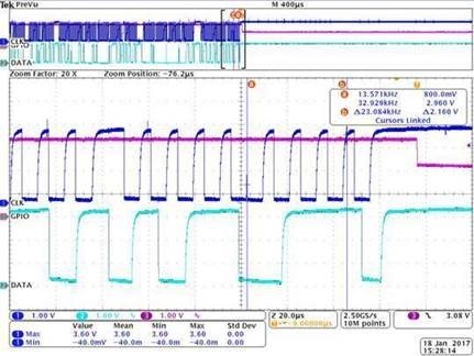
    We found that on position "a", SCL misses one clock pulled down by somewhere.

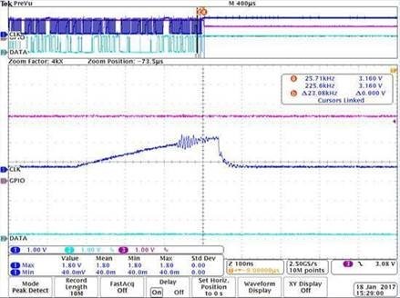
    We can't see any failure on SDA. So, I exended the SCL waveform in figure2.

    There is a glicth appeared on clock, after that clock has been pulled down by somewhere.

    This bus only connects to PSU, there is one master and one slave on the same bus.

    So far, this issue has been finished after turning on the I2C glitch filter. We suspected that clock has been pulled down by Master, but root cause might be glitch.

    Would you possibly a little bit detail why Master pulled clock down? Why we turn on glitch filter it could pass?

    Thanks

     figure 1.

     figure 2.

  • Hello Rakers

    Glitch is more than a missing clock. The board routing, noise on the adjacent signals, the pull up resistor strength all have an effect on the signal quality. The master does not generate a glitch by design as it drives the signal and monitors it on the read path. By adding a glitch filter on the path, the master ignores the false clock edge if it does not meet the requirement of width to allow to pass.
  • Hi Amit,

    We all know TTL high level is 2.3~3.3V and low level is -0.5~1V based on VDD is 3.3V.

    Would you possibly share the I2C function block of TM4C123G to us? We want to know how large attitude of glitch would affect I2C communication without glitch filter.

  • Hello Rakers

    As per the I2C specification, the maximum glitch width that may be guarded against is 50ns for 100KHz SCL rate. A glitch larger than that would be a system issue and something the device may or may not guard against.

    Any details of the block outside of the publicly available data in form of the datasheet is TI proprietary information and cannot be shared.
  • Hi Ashara,

    Sorry for annoying,

    First up,

    TM4C123G would pull down clock while glitch is happening on rising.

    It means that there is a judgement based on SCL pin even though the clock is rising.

    Could you possibly let us know why this judgement is design even in rising edge? not just in high/low level?

    I mean, it looks like when glitch happens in gray zone, this issue would happen. If it happened in high level(2.3~3.3V), SCL of TM4C123G would not pull down clock.

    Secondly,

    When clock is high, it means that TM4C123G should catch the data on SDA.

    How many times does the MCU catch for make sure the data is good?

    For example, when clock is high, TM4C123G should to catch or check that SDA is high or low. Inside of MCU should to catch 5 times or 10 times for ensuring the low is correct for avoiding noise.

    Would you possibly let us know how many times does this part catch for ensuring the data is good.

    Thanks

    Rakers Chang

  • Hello Rakers

    Glitch detection is started on every edge and not just level. The level to which it remains stable is used to identify the glitch width.

    The MCU samples the data at the start of the SCL high edge. it is a single capture and not a multiple capture.