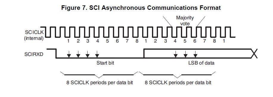
Do we have document to show how UART module to determine the each bit value? I know there are internal 16 or 8 clk samples for each bit, but how many samples could decide the bit value is 0 or 1?
This thread has been locked.
If you have a related question, please click the "Ask a related question" button in the top right corner. The newly created question will be automatically linked to this question.
Do we have document to show how UART module to determine the each bit value? I know there are internal 16 or 8 clk samples for each bit, but how many samples could decide the bit value is 0 or 1?
Hi,
Below is an excerpt from paragraph 14.3.3 of the user manual:
When the receiver is idle (the UnRx signal is continuously 1), and the data input goes Low (a start bit has been received), the receive counter begins running and data is sampled on the eighth cycle of Baud16 or fourth cycle of Baud8 depending on the setting of the HSE bit (bit 5) in UARTCTL (described in “Transmit/Receive Logic” on page 914).
The start bit is valid and recognized if the UnRx signal is still low on the eighth cycle of Baud16 (HSE clear) or the fourth cycle of Baud 8 (HSE set), otherwise it is ignored. After a valid start bit is detected, successive data bits are sampled on every 16th cycle of Baud16 or 8th cycle of Baud8 (that is, one bit period later) according to the programmed length of the data characters and value of the HSE bit in UARTCTL. The parity bit is then checked if parity mode is enabled. Data length and parity are defined in the UARTLCRH register.
cb1_mobile said:UART data was sampled & examined during "3" clock edges. That "bit level" receiving "2" (or all 3) "hits" was deemed, "valid."
Appears (some) duplication of effort. (and response) Quote (above) appeared w/in (very) first response to this thread...
Thank you, Bob. My report did target LM3S & LX4F - and as we're told that (LX4F = TM4C123) - I believed my report to enjoy (some) validity...