This thread has been locked.

If you have a related question, please click the "Ask a related question" button in the top right corner. The newly created question will be automatically linked to this question.

EK-TM4C1294XL: Why is PWM global synchronous update not producing a similar pattern in all 3 generators outputs.

Guru 54027 points
Part Number: EK-TM4C1294XL
Other Parts Discussed in Thread: TM4C1294NCPDT, INA240

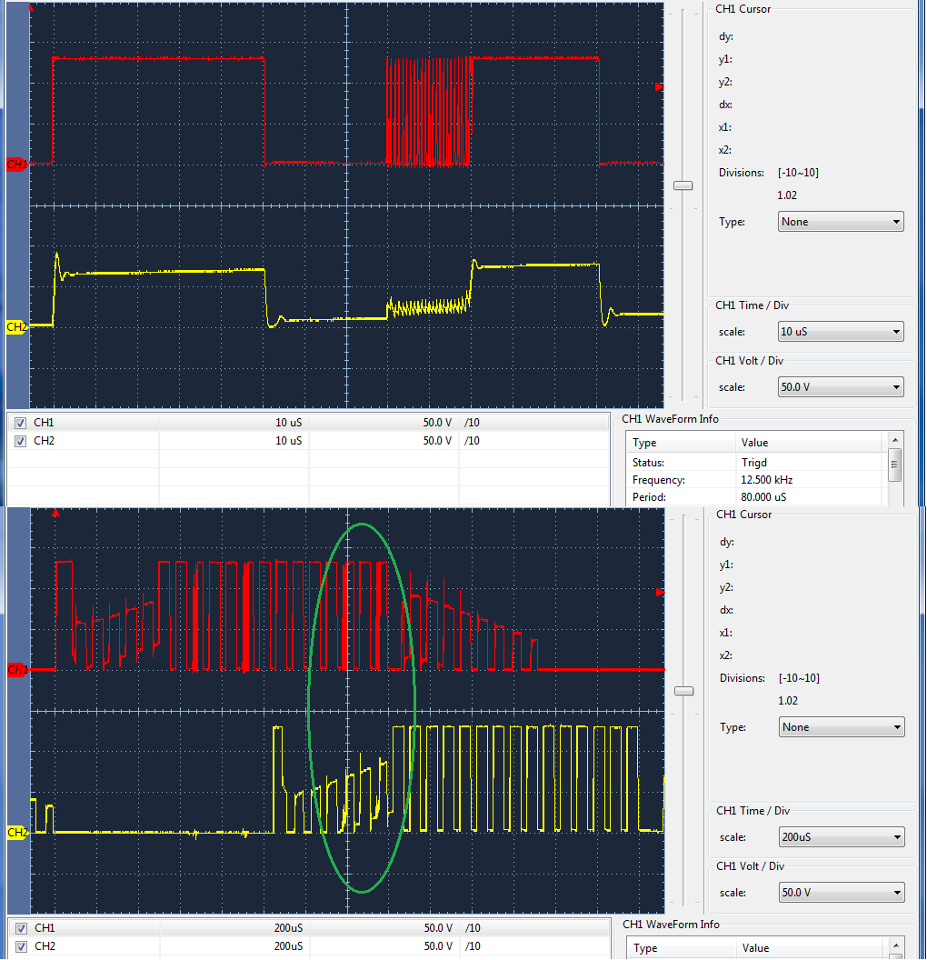
3 PWM generators 1,2,3 but only 2 modulates 80us period having active duty 50us on time (high pulse) where 240ns chopping pulses exist in first 32us of 50us on time. The other generators 1,3 never produce similar chopping pulses but do change rising/falling edge of active on times in the resulting 3 phase inverter wave form. Chopping pulses from generator 2 are seen distinctly via 3phase 1/2 bridge gate drivers reacting to the PWM generators. Otherwise 240ns chopping pulses are hard to imagine in the individual generator edge times.

Perhaps because it requires 2 PWM generators working in concert to produce a proper gate drive pattern for generating a DSP trapezoidal wave shape without 1/2 bridge shoot through occurring.

All three PWM generators are globally synchronous updated via an interrupt from generator 1 upon reaching count zero. Below is the command instructing 3 generators to perform a global synchronous update after a new count is loaded to each generator inside the interrupt handler of generator 1.

Is it wrong for me to think all 3 generators loaded with a similar count prior to an global synchronous update should be producing nearly the same 240ns chopping pulses?

ROM_PWMSyncUpdate(PWM0_BASE,
	(PWM_GEN_1_BIT|PWM_GEN_2_BIT|PWM_GEN_3_BIT));

  • A scope captures aids above post; CH1 = PWM generators 1 and 3, CH2 = 2 and 3 respectively represent two phases of 3 phase inverter 1/2 bridges, center = CH1. Liking any 240ns rising edge chopping pulses inside 50us of 80us period but don't understand why or what makes them only mostly prevalent center phase of inverter.

    CH2 reflection (green oval) seem to follow magnitude CH1 chopping pulses representing two different gate drivers. BTW: 240ns chopping pulses are roughly 14.4 ticks wide @60Mhz PWMCLK, each PWM generator can produce 4800 ticks/sec. 

  • Hi  BP101,

    BP101 said:
    the PWMCLK is running @60Mhz

      So you are setting up thePWMCLK with SYSCTL_PWMDIV_2, correct?

      It is possible that you may be hitting the below errata.

  • Hi Charles,

    Charles Tsai said:
    So you are setting up thePWMCLK with SYSCTL_PWMDIV_2, correct?

    Correct 0x2 and past posted this forum seeing CCS debug counter registers are not keeping synchronous counts yet all 3 sync bits are set. Amit at one time believed JTAG slow timing to blame but the 240ns pulses generator 2 only, certainly rises an eyebrow.

    Is it plausible we PWMSYNC time base with clock division 0x0, test for sync flag bits to set then change PWMCLK divisor 0x2 and maintain generator synchronization?

    Thanks for the quick reply :)

  • BTW these EK are all RA2 die, silicon Rev. 3 MCU.

  • Hi BP101,
    Since the errata states that there is no workaround, I don't know if your proposal will work. Besides, you will need to change the divisor to three different PWM generators at three different times as CPU can't write to all of them at the same time.
  • Hi Charles,

    Charles Tsai said:
    three different PWM generators at three different times as CPU can't write to all of them at the same time.

    Perhaps you are referring to generator synchronization, my first post shows Tivaware OR's all generators.

    The launch pad in this post has RA2 die, revision 3 silicon, not listed to have that PWM #02 known errata you mention or does it?

    Thanks

  • Hi BP101,
    Sorry, you are correct that PWM#2 should not affect RA2/RA3 according the errata.
  • Hi Charles,

    Can you confirm that is indeed true or back check to see who did that errata analysis QC?

    My idea of how PWM chopping pulse distribution might should appear similar between generators differs from the shifting positions across generators in the wave form being produced. That is to say chopping pattern repeats right, center, left, e.g. generator 1=right, 2=center, 3=left. It never wavers only that all chopping pulses disappear below a certain duty cycle update rate and coincides with current demand relative to rising rotor speed.

  • Hi BP101,
    I will check with Amit if the errata is valid for your silicon revision.
  • Hi Charles,

    That would be good to compare what is happening here to the actual test procedure used for errata #02 quality checks.

    Suspecting It might be the method of how time base must be synchronized relative PWM clock divisor to avoid having non synchronized generators in the later silicon revisions. It's really hard to know if center alignment is being maintained between all 3 generators. Have past noticed depending on the channel trigger source a generators output A could appear left, center or even right aligned relative to a copartner generator output B and visa versa.

    Thanks

  • Hi BP101,
    While I'm waiting for answer from Amit, Is it possible for you to try reducing your SYSCLK to 60MHz and keep the PWMCLK to divide by 1?
  • Hi Charles,

    Perhaps could for CCS debug register view verify 3 PWM generator counts update synchronously or not. Generator counts don't update all together now via JTAG. Will report back if any distinct difference is noticed.
  • Hi BP101,
    Amit mentioned that PWM#05 which is applicable to your silicon maybe something to look at as well.
  • Hi Charles,

    Charles Tsai said:
    Amit mentioned that PWM#05

    PWM #05 was not in Errata data SPMZ850D–October 2013–Revised March 2015, will check for updated sheet.

    Could swear posted a report yesterday about setting PWM clock 120Mhz (no divisor), made no difference nor did 60Mhz SYSCLK, register view CCS debug 3 generator counts were still uneven. Can not test Trapezoidal @60Mhz SYSCLK (no PWM divisor) as FOC and other timers are far to slow (periods) and 120Mhz PWMCLK quickly overheats inverter FETS as I recall. 

    Thanks for update!

  • Hi Charles,

    Charles Tsai said:
    Amit mentioned that PWM#05 which is applicable to your silicon maybe something to look at as well

    PWM#05; Errata appears to say down counts are affected and generators are configured in Up/Down count mode.

    Note worthy is SW double clears PWM zero interrupt prior to loading new counts and preforming global synchronous update all 3 generators.

    Seems to me the generators are not synchronously updating no matter what the PWM clock rate is made.

  • BP101 said:
    Seems to me the generators are not synchronously updating no matter what the PWM clock rate is made

    In CCS debug that is the definitive case, yet I suspect the 3 generators time base are likely very synchronous indeed.

    Question remains are all 3 counters updating simultaneously & concurrently after next zero count in a global synchronous update (GBSUD)? I suspect generator counts are not equal regardless of time base and the reason comparators A & B are triggering RCL or LCR patterns (Right, Center, Left) visa versa. 

    For that exact reason we must reset the PWM module in order to ZERO all 4 generators counters. However it seems they generators are not zeroing as the datasheet suggest they should.

    Below is how SW resets the PWM module in order to zero the counters:   

    /* Disable the PWM module */
    ROM_SysCtlPeripheralDisable(SYSCTL_PERIPH_PWM0);
    
    /* Reset the PWM module zero the counters */
    ROM_SysCtlPeripheralReset(SYSCTL_PERIPH_PWM0);
    
    /* Enable the PWM module counters at zero count */
    ROM_SysCtlPeripheralEnable(SYSCTL_PERIPH_PWM0);
    
    /* Pause here until PWM0 module is ready */
    while(!(ROM_SysCtlPeripheralReady(SYSCTL_PERIPH_PWM0)))
    {
    }
    
    /* Divide 120Mhz SYSCLK for 60Mhz PWMCLK */
    HWREG(PWM0_BASE + PWM_O_CC) = PWM_SYSCLK_DIV_2;


  • Hi BP101,

      Sorry, Could you please try to use PWMSyncTimeBase() to see if you can reset all the generators?

    Prototype:
    void
    PWMSyncTimeBase(uint32_t ui32Base,
    uint32_t ui32GenBits)
    Parameters:
    ui32Base is the base address of the PWM module.
    ui32GenBits are the PWM generator blocks to be synchronized. This parameter must be
    the logical OR of any of PWM_GEN_0_BIT, PWM_GEN_1_BIT, PWM_GEN_2_BIT, or
    PWM_GEN_3_BIT.
    Description:
    For the selected PWM module, this function synchronizes the time base of the generator blocks
    by causing the specified generator counters to be reset to zero.
    Returns:
    None.

  • Hi Charles,

    Actually HWREG and PWMSyncTimeBase()  are one in the same minus a call stack push/pop and asserts. If we can't trust an HWREG MACRO to configure peripherals we are in really big trouble. For the hake of it will give Tivaware a chance, yet more so than ever feel the PWM generators time base is indeed synchronous but the counters registers are not zeroing concurrently.

    /* Synchronize the PWM generators time bases.  */
    HWREG(PWM0_BASE + PWM_O_SYNC) = (PWM_GEN_0_BIT | PWM_GEN_1_BIT | PWM_GEN_2_BIT | PWM_GEN_3_BIT);

    Tivaware:

    //*****************************************************************************
    void
    PWMSyncTimeBase(uint32_t ui32Base, uint32_t ui32GenBits)
    {
        //
        // Check the arguments.
        //
        ASSERT((ui32Base == PWM0_BASE) || (ui32Base == PWM1_BASE));
        ASSERT(!(ui32GenBits & ~(PWM_GEN_0_BIT | PWM_GEN_1_BIT | PWM_GEN_2_BIT |
                                 PWM_GEN_3_BIT)));
    
        //
        // Synchronize the counters in the specified generators by writing to the
        // module's synchronization register.
        //
        HWREG(ui32Base + PWM_O_SYNC) = ui32GenBits;
    }

  • Hello community,

    A thought  did occur PWM chopping pulses might be a similar results PI speed regulation software working as an CCC (complex current controller).  Delfino 200Mhz dual core (TM2320-F28037xD) leveraging FCL (fast current loop) library functions with inline ADC managed PWM cycles under 500ns FOC, suggests 1us current loops regulation occurs with SAR ADC.

    Perhaps the TM4C1294NCPDT breaks the barrier @240ns FCL. For instance  with ADC @2MSPS 2x over sampling.  Three external INA240 phase current monitors (analogs) leverage a GPTM one shot (1.5us blanking) period to synchronizes ADC samples amid FOC controlled PWM cycles.

    The chopping pulses occur during PI speed regulation (software) though not an complex current controller (CCC) - or is it ??? Delfino text states CCC makes speed magic with QEC encoders using only the index pulse versus sampled EMF edges. Suspecting the CCC is actually part of the FCL control library and not specifically internal hardware as one might think is built into the Delfino hardware.

    Any thoughts?

    https://e2e.ti.com/blogs_/b/motordrivecontrol/archive/2017/06/27/unprecedented-current-loop-performance-from-an-off-the-shelf-mcu?HQS=epd-mcu-c2x-drives-nsl-blog-fclblog-wwe&DCMP=mytinwsltr_07_30_2017&userInfo=yQICQdC4GMbp7P+mWSkI1NnT+qjIbDUujZbAp2dn6rM=&article_name=epd_mcu_c2x_nsl_fclblog&newsletter=23-JUL-17&eloquaCampaignId=522&utm_campaign=myTI%20newsletter%202017-07-30&utm_medium=email&utm_source=Eloqua