Part Number: EK-TM4C1294XL
Other Parts Discussed in Thread: TM4C1294NCPDT, ADS7142,
Hello,
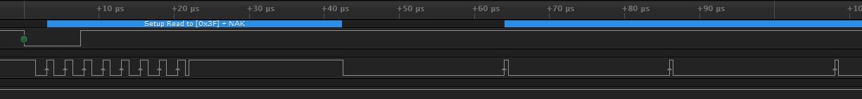
I have attached the TM4C1294NCPDT datasheet for reference into the following issue as well as the ADS7142 datasheet. The following code should place the ADS7142 in Manual Mode scanning CH0 only. However, stepping through the code in Code Composer Studio is showing that the master MCU is losing i2c bus arbitration for whatever reason. This error does not seem to make sense in a single-master system but it is the error since my error check routine in the code is where the debugger is getting stuck.
On pages 1291-1293 are the Master Tx/Rx software flow charts I have used to develop the three functions I call in main. The code is getting stuck inside the first call of ADS7142SingleRegisterWrite().
Any insight as to this problem is appreciated, thanks
//*****************************************************************************
//
// ADS7142_ManualMode_CH0Scan.c - Example demonstrating a simple I2C
// transmission and reception.
//
// Copyright (c) 2010-2016 Texas Instruments Incorporated. All rights reserved.
// Software License Agreement
//
// Redistribution and use in source and binary forms, with or without
// modification, are permitted provided that the following conditions
// are met:
//
// Redistributions of source code must retain the above copyright
// notice, this list of conditions and the following disclaimer.
//
// Redistributions in binary form must reproduce the above copyright
// notice, this list of conditions and the following disclaimer in the
// documentation and/or other materials provided with the
// distribution.
//
// Neither the name of Texas Instruments Incorporated nor the names of
// its contributors may be used to endorse or promote products derived
// from this software without specific prior written permission.
//
// THIS SOFTWARE IS PROVIDED BY THE COPYRIGHT HOLDERS AND CONTRIBUTORS
// "AS IS" AND ANY EXPRESS OR IMPLIED WARRANTIES, INCLUDING, BUT NOT
// LIMITED TO, THE IMPLIED WARRANTIES OF MERCHANTABILITY AND FITNESS FOR
// A PARTICULAR PURPOSE ARE DISCLAIMED. IN NO EVENT SHALL THE COPYRIGHT
// OWNER OR CONTRIBUTORS BE LIABLE FOR ANY DIRECT, INDIRECT, INCIDENTAL,
// SPECIAL, EXEMPLARY, OR CONSEQUENTIAL DAMAGES (INCLUDING, BUT NOT
// LIMITED TO, PROCUREMENT OF SUBSTITUTE GOODS OR SERVICES; LOSS OF USE,
// DATA, OR PROFITS; OR BUSINESS INTERRUPTION) HOWEVER CAUSED AND ON ANY
// THEORY OF LIABILITY, WHETHER IN CONTRACT, STRICT LIABILITY, OR TORT
// (INCLUDING NEGLIGENCE OR OTHERWISE) ARISING IN ANY WAY OUT OF THE USE
// OF THIS SOFTWARE, EVEN IF ADVISED OF THE POSSIBILITY OF SUCH DAMAGE.
//
// This is part of revision 2.1.3.156 of the Tiva Firmware Development Package.
//
//*****************************************************************************

#include <stdbool.h>
#include <stdint.h>
#include "inc/hw_i2c.h"
#include "inc/hw_memmap.h"
#include "inc/hw_types.h"
#include "driverlib/gpio.h"
#include "driverlib/i2c.h"
#include "driverlib/i2c.c"
#include "driverlib/pin_map.h"
#include "driverlib/sysctl.h"
#include "driverlib/uart.h"
#include "utils/uartstdio.h"
#include "ADS7142registermap.h"


//*****************************************************************************
//
//! \addtogroup i2c_examples_list
//!
//!
//! This example shows how to configure the I2C8 module for connection/communication
//! with the ADS7142 Boosterpack.
//! This includes setting up the master and slave module. Loopback mode
//! internally connects the master and slave data and clock lines together. This example
//! does not use loopback mode is communication is being performed with an external device
//! to the TM4C1294NCPDT microcontroller.
//! The address of the slave module is set in order to read data from the
//! master. Then the data is checked to make sure the received data matches
//! the data that was transmitted. This example uses a polling method for
//! sending and receiving data.
//!
//! This example uses the following peripherals and I/O signals. You must
//! review these and change as needed for your own board:
//! - I2C8 peripheral
//! - GPIO Port A peripheral (for I2C8 pins)
//! - I2C8SCL - PA2
//! - I2C8SDA - PA3
//!
//! This example uses the following interrupt handlers. To use this example
//! in your own application you must add these interrupt handlers to your
//! vector table.
//! - None.
//
//*****************************************************************************


//*****************************************************************************
//
// Set the address for slave module. This is a 7-bit address sent in the
// following format:
// [A6:A5:A4:A3:A2:A1:A0:RS]
//
// A zero in the "RS" position of the first byte means that the master
// transmits (sends) data to the selected slave, and a one in this position
// means that the master receives data from the slave. The slave address of
// the ADS7142 in this example is set by hardware on the ADS7142boostxl
//
//*****************************************************************************
#define SLAVE_ADDRESS 0x18

void
ADS7142SingleRegisterWrite (uint8_t RegisterAddress, uint8_t RegisterData)
{
	//ADS7142 Single Register Write

	//
	// Tell the master module what address it will place on the bus when
	// communicating with the slave. Set the address to SLAVE_ADDRESS
	// (as set in the slave module). The receive parameter is set to false
	// which indicates the I2C Master is initiating a writes to the slave. If
	// true, that would indicate that the I2C Master is initiating reads from
	// the slave.
	//

	I2CMasterSlaveAddrSet(I2C8_BASE, SLAVE_ADDRESS, false);

	//Place the first byte to be transmitted into the I2CMDR Register of the TM4C1294
	//The first byte to be transmitted following the SLAVE Address is the Single Register Write opcode
	I2CMasterDataPut(I2C8_BASE, SINGLE_WRITE);

	//Check the I2C Bus to ensure it is not busy
	while(I2CMasterBusBusy(I2C8_BASE))

	{
		//Read I2CMCS
	}

	//I2C Master Command for the Start of BURST Send of 3 bytes
	I2CMasterControl(I2C8_BASE, I2C_MASTER_CMD_BURST_SEND_START);

	//Implement delay
	SysCtlDelay(100);

	//Wait for the I2CMaster to finish transmitting before moving to next byte
	while(I2CMasterBusy(I2C8_BASE))

	{
		//Read I2CMCS
	}

	//Check for errors in the I2C8 Module
	while (I2CMasterErr(I2C8_BASE) != I2C_MASTER_ERR_NONE)

		//Error branching
	{

		//Check for Arbitrary Lost error condition
		if(I2CMasterErr(I2C8_BASE) == I2C_MASTER_ERR_ARB_LOST)

		{
			//Error service
		}

		//Write I2C Master Command for receive error stop
		else if (I2CMasterErr(I2C8_BASE) != I2C_MASTER_ERR_ARB_LOST)

		{

			I2CMasterControl(I2C8_BASE, I2C_MASTER_CMD_BURST_RECEIVE_ERROR_STOP);

			//Implement Delay
			SysCtlDelay(100);

			{
				//Error service
			}

		}
	}

	//Place the next byte into I2CMDR, the register address of desired data write
	I2CMasterDataPut(I2C8_BASE, RegisterAddress);

	//I2C Master Command for continued BURST send of the next byte
	I2CMasterControl(I2C8_BASE, I2C_MASTER_CMD_BURST_SEND_CONT);

	//Implement Delay
	SysCtlDelay(100);

	//Wait for the I2CMaster to finish transmitting before moving to next byte
	while(I2CMasterBusy(I2C8_BASE))

	{
		//Read I2CMCS
	}

	//Check for errors in the I2C8 Module
	while (I2CMasterErr(I2C8_BASE))

		//Error branching
	{


		//Check for Arbitrary Lost error condition
		if(I2CMasterErr(I2C8_BASE) == I2C_MASTER_ERR_ARB_LOST)

		{
			//Error service
		}

		//Write I2C Master Command for receive error stop
		else if (I2CMasterErr(I2C8_BASE) != I2C_MASTER_ERR_ARB_LOST)
		{

			I2CMasterControl(I2C8_BASE, I2C_MASTER_CMD_BURST_RECEIVE_ERROR_STOP);

			//Implement Delay
			SysCtlDelay(100);

			{
				//Error service
			}

		}
	}


	//Place the final byte into I2CMDR, the register data to be placed in the desired register address
	I2CMasterDataPut(I2C8_BASE, RegisterData);

	//I2C Master Command for the finished BURST send of the data
	I2CMasterControl(I2C8_BASE, I2C_MASTER_CMD_BURST_SEND_FINISH);

	//Implement delay
	SysCtlDelay(100);

	//Wait for the I2C Master to finish transmitting
	while(I2CMasterBusy(I2C8_BASE))

	{
		//Read I2CMCS
	}

	//Check the error flag in the I2C8 Module
	while (I2CMasterErr(I2C8_BASE))

	{
		//Error service
	}

}

void
ADS7142SingleRegisterRead(uint8_t RegisterAddress)
{
	//ADS7142 Single Register Read
	//
	// Tell the master module what address it will place on the bus when
	// communicating with the slave. Set the address to SLAVE_ADDRESS
	// (as set in the slave module). The receive parameter is set to false
	// which indicates the I2C Master is initiating a writes to the slave.
	// To perform a register read, the Master must first transmit the desired SLAVE address for communication.
	// Following the Slave address, the single register read opcode will be transmitted.
	// If true, that would indicate that the I2C Master is initiating reads from
	// the slave.
	//
	//
	I2CMasterSlaveAddrSet(I2C8_BASE, SLAVE_ADDRESS, false);

	//Place the Single Register Read opcode into the I2CMDR Register
	I2CMasterDataPut(I2C8_BASE, SINGLE_READ);

	//Check the I2C Bus to ensure it is not busy
	while(I2CMasterBusBusy(I2C8_BASE))

	{
		//Read I2CMCS
	}

	//Initiate the BURST Send of two data bytes
	I2CMasterControl(I2C8_BASE, I2C_MASTER_CMD_BURST_SEND_START);

	//Implement Delay
	SysCtlDelay(100);

	//Wait for the I2C Master to finish transmitting
	while(I2CMasterBusy(I2C8_BASE))

	{
		//Read I2CMCS
	}

	//Check for errors in the I2C8 Module
	while (I2CMasterErr(I2C8_BASE))

		//Error branching
	{

		//Check for Arbitrary Lost error condition
		if(I2CMasterErr(I2C8_BASE) == I2C_MASTER_ERR_ARB_LOST)

		{
			//Error service
		}

		//Write I2C Master Command for receive error stop
		else if (I2CMasterErr(I2C8_BASE) != I2C_MASTER_ERR_ARB_LOST)
		{

			I2CMasterControl(I2C8_BASE, I2C_MASTER_CMD_BURST_RECEIVE_ERROR_STOP);

			//Implement Delay
			SysCtlDelay(100);

			{
				//Error service
			}

		}

	}

	//Place the Register Address to be communicated with into the I2CMDR Register
	I2CMasterDataPut(I2C8_BASE,RegisterAddress);

	//I2C Master Command for finished Burst Send of the two bytes required for register read
	I2CMasterControl(I2C8_BASE, I2C_MASTER_CMD_BURST_SEND_FINISH);

	//Implement Delay
	SysCtlDelay(100);

	//Wait for the I2C Master to finish transmitting the data
	while(I2CMasterBusy(I2C8_BASE))

	{
		//Read I2CMCS
	}

	//Check the error flag in the I2C8 Module
	while(I2CMasterErr(I2C8_BASE))

	{
		//Error service
	}

	//Set the receive parameter to true in order to receive data from the desired register address
	I2CMasterSlaveAddrSet(I2C8_BASE, SLAVE_ADDRESS, true);

	//Check the I2C Bus to ensure it is not busy
	while(I2CMasterBusBusy(I2C8_BASE))

	{
		//Read I2CMCS
	}

	//I2C Master Command for the Single Byte Receive from the register address
	I2CMasterControl(I2C8_BASE, I2C_MASTER_CMD_SINGLE_RECEIVE);

	//Implement Delay
	SysCtlDelay(100);

	//Wait for the I2C Master to finish transmitting the data
	while(I2CMasterBusy(I2C8_BASE))

	{
		//Read I2CMCS
	}

	//Check the error flag in the I2C8 Module
	while(I2CMasterErr(I2C8_BASE))

	{
		//Error service
	}

	//Get the data placed into the I2CMDR Register from the ADS7142
	I2CMasterDataGet(I2C8_BASE);
}

void
StartSampling()
{
	//Provide Device Address and Read Bit to Start Conversions
	I2CMasterSlaveAddrSet(I2C8_BASE, SLAVE_ADDRESS, true);

	//Check the I2C Bus to ensure it is not busy
	while(I2CMasterBusBusy(I2C8_BASE))

	{
		//Read I2CMCS
	}

	//Write the Burst receive I2C Master Command to I2CMCS
	I2CMasterControl(I2C8_BASE, I2C_MASTER_CMD_BURST_RECEIVE_START);

	//Implement Delay
	SysCtlDelay(100);

	{
		//Read I2CMCS
	}

	//Allow the Master to finish receiving the first byte
	while(I2CMasterBusy(I2C8_BASE))

	{
		//Read I2CMCS
	}

	//Check for errors in the I2C8 Module
	while (I2CMasterErr(I2C8_BASE))

		//Error branching
	{

		//Check for Master Arbitration Lost error condition
		if(I2CMasterErr(I2C8_BASE) == I2C_MASTER_ERR_ARB_LOST)

		{
			//Error service
		}

		//Write I2C Master Command for receive error stop
		else if (I2CMasterErr(I2C8_BASE) != I2C_MASTER_ERR_ARB_LOST)
		{

			I2CMasterControl(I2C8_BASE, I2C_MASTER_CMD_BURST_RECEIVE_ERROR_STOP);

			//Implement Delay
			SysCtlDelay(100);

			{
				//Error service
			}

		}

	}

	//Read data from I2CMDR
	I2CMasterDataGet(I2C8_BASE);

	while(1)
	{

		//Continue receiving the burst data
		I2CMasterControl(I2C8_BASE, I2C_MASTER_CMD_BURST_RECEIVE_CONT);

		//Implement Delay
		SysCtlDelay(100);

		{
			//Read I2CMCS
		}

		//Allow the Master to finish receiving each byte
		while(I2CMasterBusy(I2C8_BASE))

		{
			//Read I2CMCS
		}

		//Check for errors in the I2C8 Module
		while (I2CMasterErr(I2C8_BASE) != I2C_MASTER_ERR_NONE)

			//Error branching
		{

			//Check for Arbitrary Lost error condition
			if(I2CMasterErr(I2C8_BASE) == I2C_MASTER_ERR_ARB_LOST)

			{
				//Error service
			}

			//Write I2C Master Command for receive error stop
			else if (I2CMasterErr(I2C8_BASE) != I2C_MASTER_ERR_ARB_LOST)
			{

				I2CMasterControl(I2C8_BASE, I2C_MASTER_CMD_BURST_RECEIVE_ERROR_STOP);

				//Implement Delay
				SysCtlDelay(100);

				{
					//Error service
				}

			}

		}

	}
}
//*****************************************************************************
//
// Configure the I2C8 master and slave and connect them to the ADS7142 Boosterpack
//
//*****************************************************************************
int
main(void)
{
#if defined(TARGET_IS_TM4C129_RA0) || \
		defined(TARGET_IS_TM4C129_RA1) || \
		defined(TARGET_IS_TM4C129_RA2)
	uint32_t ui32SysClock;
#endif

	//
	// Set the clocking to run directly from the external crystal/oscillator.
	// TODO: The SYSCTL_XTAL_ value must be changed to match the value of the
	// crystal on your board.
	//
#if defined(TARGET_IS_TM4C129_RA0) || \
		defined(TARGET_IS_TM4C129_RA1) || \
		defined(TARGET_IS_TM4C129_RA2)
	ui32SysClock = SysCtlClockFreqSet((SYSCTL_XTAL_25MHZ |
			SYSCTL_OSC_MAIN |
			SYSCTL_USE_OSC), 25000000);
#else
	SysCtlClockSet(SYSCTL_SYSDIV_1 | SYSCTL_USE_OSC | SYSCTL_OSC_MAIN |
			SYSCTL_XTAL_16MHZ);
#endif

	//
	// The I2C8 peripheral must be enabled before use.
	//
	SysCtlPeripheralEnable(SYSCTL_PERIPH_I2C8);

	//
	// For this example I2C8 is used with PortA[3:2]. The actual port and
	// pins used may be different on your part, consult the data sheet for
	// more information. GPIO port A needs to be enabled so these pins can
	// be used.
	// TODO: change this to whichever GPIO port you are using.
	//
	SysCtlPeripheralEnable(SYSCTL_PERIPH_GPIOA);

	//
	// Configure the pin muxing for I2C8 functions on port A2 and A3.
	// This step is not necessary if your part does not support pin muxing.
	// TODO: change this to select the port/pin you are using.
	//
	GPIOPinConfigure(GPIO_PA2_I2C8SCL);
	GPIOPinConfigure(GPIO_PA3_I2C8SDA);

	//
	// Select the I2C function for these pins. This function will also
	// configure the GPIO pins pins for I2C operation, setting them to
	// open-drain operation with weak pull-ups. Consult the data sheet
	// to see which functions are allocated per pin.
	// TODO: change this to select the port/pin you are using.
	//
	GPIOPinTypeI2CSCL(GPIO_PORTA_BASE, GPIO_PIN_2);
	GPIOPinTypeI2C(GPIO_PORTA_BASE, GPIO_PIN_3);

	//
	//Enable master interrupts. This function will enable all interrupts
	//available to the I2C Master.
	// I2CMasterIntEnable(I2C8_BASE);
	// I2CSlaveIntEnable(I2C8_BASE);

#if defined(TARGET_IS_TM4C129_RA0) || \
		defined(TARGET_IS_TM4C129_RA1) || \
		defined(TARGET_IS_TM4C129_RA2)
	I2CMasterInitExpClk(I2C8_BASE, ui32SysClock, false);
#else
	I2CMasterInitExpClk(I2C8_BASE, SysCtlClockGet(), false);
#endif


	//Let's put the device into Manual Mode with a Single Channel Single-Ended Configuration
	//for conversion of data

	//Select the channel input configurations
	ADS7142SingleRegisterWrite(ADS7142_REG_CHANNEL_INPUT_CFG, ADS7142_VAL_CHANNEL_INPUT_CFG_1_CHANNEL_SINGLE_ENDED);

	//Confirm the input channel configuration
	ADS7142SingleRegisterRead(ADS7142_REG_CHANNEL_INPUT_CFG);

	//Select the operation mode of the device
	ADS7142SingleRegisterWrite(ADS7142_REG_OPMODE_SEL, ADS7142_VAL_OPMODE_SEL_I2C_CMD_MODE_W_CHANNEL_0);

	//Confirm the operation mode selection
	ADS7142SingleRegisterRead(ADS7142_REG_OPMODE_SEL);

	//Begin manual mode operation
	//Start Scanning Ch0
	StartSampling();

	return(0);

}