This thread has been locked.

If you have a related question, please click the "Ask a related question" button in the top right corner. The newly created question will be automatically linked to this question.

CCS: No wavefrom coming on CAN Bus Debug Error: _c_int00() at boot.asm:227 0x00000C5A(_c_int00 does not contain frame information)

Tool/software: Code Composer Studio

Hi all,

I am working CAN module. Previously I created thread regarding CAN module issue: 

This issue was resolved and I was getting proper CAN frame at output. 

Further I added ADC code. After this modification my code was working and CAN frames coming out at PB1. 

Code is as follows

#include <stdint.h>
#include <stdbool.h>
#include "inc/hw_memmap.h"
#include "inc/hw_types.h"
#include "inc/hw_can.h"
#include "inc/hw_ints.h"
#include "driverlib/debug.h"
#include "driverlib/sysctl.h"
#include "driverlib/gpio.h"
#include "driverlib/adc.h"
#include "driverlib/can.h"
#include "driverlib/interrupt.h"
#include "driverlib/pin_map.h"
#include "driverlib/sysctl.h"


uint32_t ui32ACCValues1=0;
uint32_t ui32ACCavg1;
uint8_t Count=0;
uint32_t ui32SysClock=0;
volatile bool g_bErrFlag = 0;
volatile bool g_bTXFlag = 0;

void SimpleDelay(void)
{
    SysCtlDelay(40000);
}

void CANIntHandler(void)
{
    uint32_t ui32Status;
    ui32Status = CANIntStatus(CAN0_BASE, CAN_INT_STS_CAUSE);
   if(ui32Status == CAN_INT_INTID_STATUS)
    {
        ui32Status = CANStatusGet(CAN0_BASE, CAN_STS_CONTROL);
        g_bErrFlag = 1;
    }

    else if(ui32Status == 1)
    {
        CANIntClear(CAN0_BASE, 1);
        CANMessageClear(CAN0_BASE, 1);
        g_bErrFlag = 0;
        g_bTXFlag = 1;
    }
    else
    {
    }
}


int main(void)

{

    uint32_t ui32MsgData=0;
    uint8_t *pui8MsgData;
    pui8MsgData = (uint8_t *)&ui32MsgData;
    tCANMsgObject sCANMessage;
    sCANMessage.ui32MsgID = 1;
    sCANMessage.ui32MsgIDMask = 0;
    sCANMessage.ui32Flags = MSG_OBJ_TX_INT_ENABLE;
    sCANMessage.ui32MsgLen = sizeof(pui8MsgData);
    sCANMessage.pui8MsgData = pui8MsgData;


    ui32SysClock = SysCtlClockFreqSet((SYSCTL_XTAL_25MHZ | SYSCTL_OSC_MAIN | SYSCTL_USE_PLL | SYSCTL_CFG_VCO_480), 120000000);  

    SysCtlPeripheralEnable(SYSCTL_PERIPH_GPIOD);
    SysCtlPeripheralEnable(SYSCTL_PERIPH_GPIOA);
    SimpleDelay();

    GPIOPinConfigure(GPIO_PA0_CAN0RX);
    GPIOPinConfigure(GPIO_PA1_CAN0TX);
    GPIOPinTypeCAN(GPIO_PORTA_BASE, GPIO_PIN_0 | GPIO_PIN_1);

    SysCtlPeripheralEnable(SYSCTL_PERIPH_ADC1);
    SysCtlPeripheralEnable(SYSCTL_PERIPH_CAN0);
    GPIOPinTypeADC(GPIO_PORTD_BASE, GPIO_PIN_5); //PD5-CH6-Temperature
    ADCClockConfigSet(ADC1_BASE, ADC_CLOCK_SRC_PLL | ADC_CLOCK_RATE_FULL,15);
    ADCSequenceConfigure(ADC1_BASE, 3, ADC_TRIGGER_ALWAYS, 0);
    ADCSequenceStepConfigure(ADC1_BASE, 3, 0, ADC_CTL_CH6|ADC_CTL_IE|ADC_CTL_END); //REV.Pow

    CANInit(CAN0_BASE);SimpleDelay();
    CANBitRateSet(CAN0_BASE, 120000000, 1000000);SimpleDelay();

    ADCSequenceEnable(ADC1_BASE, 3);
    ADCIntClear(ADC1_BASE, 3);

    CANIntRegister(CAN0_BASE, CANIntHandler);SimpleDelay();
    CANIntEnable(CAN0_BASE, CAN_INT_MASTER | CAN_INT_ERROR | CAN_INT_STATUS);SimpleDelay();
    IntEnable(INT_CAN0);SimpleDelay();
    CANEnable(CAN0_BASE);SimpleDelay();


    Count=0;
    ui32ACCavg1=0;
    g_bTXFlag=1;

    while(1)
        {
            while(g_bTXFlag)
            {
                g_bTXFlag=0;
                Count=0;
                while(Count<10)
                {
                    while(!ADCIntStatus(ADC1_BASE, 3, false))
                    {
                    }
                    ADCSequenceDataGet(ADC1_BASE, 3,&ui32ACCValues1);
                    ADCIntClear(ADC1_BASE, 3);
                    ui32ACCavg1=ui32ACCavg1+ui32ACCValues1;
                    Count++;
                }
                ui32MsgData=ui32ACCavg1/10;
                CANMessageSet(CAN0_BASE, 1, &sCANMessage, MSG_OBJ_TYPE_TX);
                ui32ACCavg1=0;
                SimpleDelay();
            }

        }
}

Now same code is not working. No CAN frames are coming.

I have 4 spare board 2 in use and 2 new(box pack).

I tried to reprogram this 4 spare board with this code and simple TX code which I mention in my previous thread. Still i cant see CAN frames coming out.

PB1 pin is at 3.3V alwasys.

All boards are working as I reprogram with ADC code.I am getting proper output. 

LED blinking code is alo running. I tried to toggle PB0& PB1 pin and its working fine.I got square ware at output .

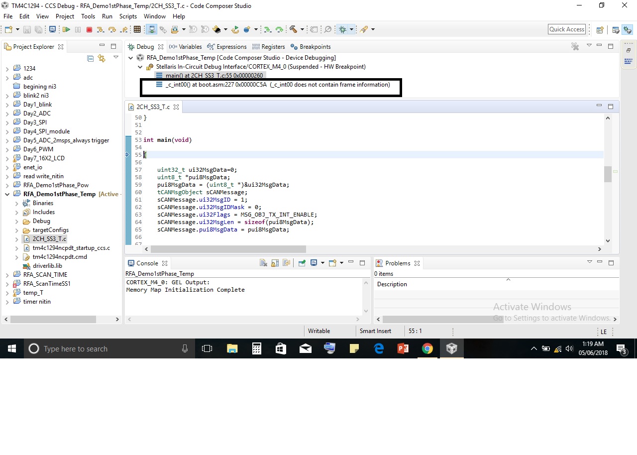
From the day, CAN is not working I get error at debugging as : c_int00() at boot.asm:227 0x00000C5A(_c_int00 does not contain frame information


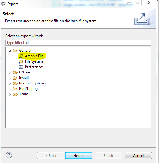
Debug error and setting in CCS are in below pics:

 issue.rar

Hope this issue will resolve soon

  • I can't tell what is wrong from the pictures you sent. Do you mind exporting your project to a .zip file and uploading it?

    File -> Export

  • Hi bob,

    Thanx for quick reply. please find zip file.ZIPcode.zip

    Regards,

    Krishnat

  • The project "RFA_Demo1stPhase_Temp" worked for me. I notice you changed the CAN baud rate from 100KB to 1MB. Did you remember to change the baud rate of all other nodes on the network?
  • Hi Bob,

    I have set 1mbsp baud rate for all nodes.

    But currently I have not connected all nodes to network. I tried to program RFA_Demo1stPhase_Temp project and saw output on PB1 pin but as of now no CAN frame is there. As no other node is there in network to receive, there should be continuous transmission untill time out.

    As I can see 3.3V at PB1 pin continuously.

    I think I have made mistake in settings of  project.

    Please go through issue.zip. it contains screenshots of setting in CCS.

    Else send me screenshots of ur project setting in CCS. I think there is mistake in debug session.

    Regards

    Krishnat

  • Lines 74 and 75 of 2CH_SS3_T.c configure CAN0 on PA0 and PA1, not PB1.
  • Sorry Bob,

    Primarily I configure For CAN1 module but no output on PortB so I configure for CAN0 and posted that code.

    But no output on PA1 pin also.

    In this case I carefully change jumper position also.

    For any Module CAN0 or CAN1 no output on pins.

    Even  I tried to program TM4C123 board with considering there pinout but same story repeats. CAN pin held to 3.3 V.

    Regards.

    Krishnat

  • Hi Bob,

    I need help urgently.
    Can module is not working.
    If this is hardware fault then Can I get new launchpad in replacement.
    I think only way to communicate with TI is this forum. No technical support is provided at customer end.

    Regards
    KRISHNAT
  • Sorry you are still having trouble. I can point you to directions on how to return your launchpad if it is truly a defective board. I need to know if you purchased if from the TI store or from a distributor.

    I suggest we try a few things first. Can you send me your latest code as an exported .zip project? Also tell me what you have connected to your launchpad and how the jumpers are set. I see in the project RFA_Demo1stPhase_Temp that you sent earlier, the CANTX pin (PA1) stops after a short time as it goes bus-off due to no acknowledge when not connected to a valid CAN bus.
  • Hey Bob,

    I have already send you project. I have pasted code, same code I am using only change is CAN1.

    All jumpers are in default position.

    I have total 6 launchpads, when I debug, code doesn't go in ISR for 5 boards. Out of five, one board showing 5 v on PB1 pin. It might because of usb pins multiplex with CAN module.

    And for 6th launchpad it goes in ISR, 1st after Canenable() function. Here ui32status=5 after it come out ISR.

    2nd time it goes in ISR after CANMmessageset() function ,here ui32status=229 after it comes out ISR.

    Lastly, you mentioned that my code works on your hardware. You see can frames. As no receiver is present bus goes off after some time. This is perfect.

    It might be possible that I have wrong settings in CCS or version of CCS and tivaware I am using may have bug. So can you please send me setting of CCS and tell me version of CCS and tivaware you are using

  • One more thing is, All of these boards are purchased from ti store.

    As per our project design one module requires 5 TM4C1294 launchpad.
    Such 4 modules are there.
    And another submodule requires 4 launchpads.

    I have designed DAQ boards for sensors. We have NI hardware for further processing.
    CAN communication is between launchpad and NI hardware.
    Now problem is launchpad CAN module only not working and rest part is working. And I have to deliver this project end of July.

    If this issue doesn't solve, I have to pick controller card from other companies. As I can't trust.
    Yesterday I went to other departments they are working on same launchpad. I took same code as above with modification is here I used CAN1 instead CAN0. On there system , on there launchpad my code doesn't work either.
    If possible help me out..
    Regards
    KRISHNAT