This thread has been locked.

If you have a related question, please click the "Ask a related question" button in the top right corner. The newly created question will be automatically linked to this question.

DRV8306: Hall Sensor Input Pin Damage

Part Number: DRV8306
Other Parts Discussed in Thread: DRV8353, DRV8350

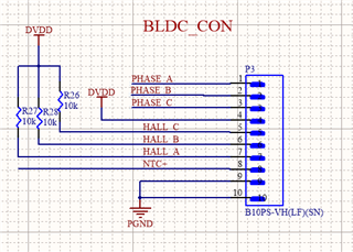
 This is the second Issue (First issue resolved from TI ) which i have found while using the DRV8306 after 6 months. While testing i found that if one of the Hall sensor Input Either HALL A, B or C is disconnected and the motor start operating (Ideally if one of the hall sensor is not changing state from logic 1 to 0 and vice versa over one period of commutation the IC Should give NFAULT INDICATION and stop commutation but this does not happen and the motor continues to operate.) If the hall sensor is then again connected the hall sensor state at IC pin is not changing (Please Note: The hall sensor of the motor used for Testing are perfectly fine and proper voltage level of 3V3 is observed when tested Seperately.

Since the HALL A, B or C input pin was constantly held on ground state i.e. Logic 0, I Checked the Resistance between the pin and Ground and I Found that the Resistance is 68 ohm. When I tested with a fresh working piece in which proper waveform was observed on all 3 HALL Pin, I Found that the Resistance between ground and pin is  about 25K ohm. Again when i conducted the same test by disconnecting hall sensor. The motor operated and after turning off the power i checked the resistance THE RESISTANCE DROPPED TO 68 OHM. This is a serious problem which i am facing in production. The hall sensor getting disconnected due to loose harness and causing damage to the Hall sensor Pin is a Serious Issue.

I Request you to please provide a solution to solve this problem ASAP. Once the pin is Damaged the IC is of no use since it does not generate proper Hall sensor waveform.

  • Hi Nikhil,

    We will work with you to figure out the root cause of this issue. First, what hall configuration are you using in your design? I have included images of the different configurations below. More information can be found in section 8.1.1 of the datasheet.

    Is it just the HPx pins that are damaged (showing the 68 ohm) or is the HNx pins also damaged? Do you have a bypass capacitor between the HPx and HNx pins?

    Regards,

    Anthony 

  • Hello Anthony,

    I am Using the hall sensor in the Configuration shown in Figure 29. Also Please note that i am using Single ended Hall sensor, the NOT signals of Hall sensor are tied to 1.7V which is formed by using a Voltage divider between DVDD(3V3 in this case) and GND two Resistor of 10K 0603 Package which is also used in the DRV8306 EVM. I am using the bypass capacitor of 1nf 0603 package. 

    I have Attached the Schematic for your reference Please let me know the problem. 

  • Hello Nikhil,

    If possible can you also provide the schematic for the Hall Sensor part of the circuit? Are your Hall Sensors open drain or analog output?

    Thanks,

    Matt

  • My Hall Sensors are Open Drain they are pulledup using a 10K 0603 Resistor as shown in the Below figure

  • Hi Nikhil,

    While disconnecting something from a working board or connecting it back there are a few things that may happen and may damage IC. Most common is ESD, second - disconnecting wires that carry current and have some inductance from circuit can cause voltage transient L*di/dt, third - there may be potential difference caused by power supply supplying the board. Lots of power supplies have second class insulation and are not grounded and have potential somewhere in the middle of neutral and phase of power grid (plus some common mode noise). ICs usually are equipped only with basic internal ESD protection for handling during pcb assembly but it may not be sufficient for disconnection/connection operations.

    Regards,

    Grzegorz

  • Dear Grzegorz,

       I am not making any connection/disconnection while the power is on, I am doing in power off state only. Also i have checked the Resistance between Hall pin and Ground in off State the IC which is good Shows 25K DAMAGED ONE SHOWS 68 OHM

  • Nikhil,

    Thanks for clarification, then from the 3 mentioned possible cases only ESD remains and some TVS diodes close to connector may help.

    There might be other reasons for IC failure that I am not aware off.

    Grzegorz

  • But I am Testing on ESD Safe MAT and also i have tested this with 3 Different working Board by Disconnecting Different HALL A B and C in each one of them but the same issue persists.

  • If failure occurs after a period when motor was working another possible cause would be transients caused by di/dt in motor cables. If hall sensor cables are close enough to motor cables and are not shielded and impedance of hall sensor inputs is quite high voltage spikes can be induced in hall sensor cables. To verify that it would be necessary to check waveforms at hall sensor input while motor is working with an oscilloscope and probe of BW at least 60-100MHz. If it is a case some RC filters might work.

  • Ok Grzegor Pelinkan I will make a video of

    A) With All Hall Sensor properly Connected with Probe Connected to one Hall Sensor and Motor is Working

    B) With one Hall Sensor Disconnected and Probe Connected to Input Pin at Motor Startup

    C) I Have one Question why is the IC not generating NFAULT in one Commutation Cycle if the State of one of the Hall sensor is not Changing. This lead to the doubt that if PIN is damaged then does the IC skip the commuation steps as shown in the Figure. 

  • I can only try to help you with external components, connections, electromagnetic interferences and probably with pcb layout. I do not know DRV8306, the questions about its working principles will be better managed by TI engineers.

  • Can those Engineer connect to this thread??

    This issue is Urgent as it is being used in Production.

    Also I would like to explore whether this problem occurs with DRV8350 and DRV8353 as I am Planning to order EVM for these to check whether this Problem exist in those.

  • Hi Nikhil,

    A couple questions for you:

    1. Is there any traces that are routed underneath or near the hall sensor traces, especially high voltage switching traces such as SHx, GHx, or GLx? I wonder if there possibly could be an issue with the switching of a high voltage signal that is coupling onto the hall signal and is especially vulnerable when the hall trace is floating. This could cause the abs max rating of the hall pin to be violated and could cause an internal short in the device. 

    2. Have you tried to use a bypass capacitor between the HPx and HNx pins located near the device to see if this resolves the issue?

    Regards,

    Anthony 

  • Dear Anthony,

    1)The Hall Traces are isolated from the Power switching planes and traces, Also the Hall sensor INPUT pin is NOT FLOATING it is pulled up using a 10K 0603 Resistor.

    2) As per above Schematic Diagram there is Bypass capacitor Present Between the Pin this Schematic is almost similar to the one used in DRV8306 EVM.

    3) If the Hall pin getting short internally then why the IC is not generating NFAULT please Clarify.

  • Hi Nikhil,

    Don't worry, we're here too (TI'ers). Anthony is a motor drive applications engineer.

    Thanks,

    Matt

  • Hi Nikhil,

    Below is a table showing the various faults that the DRV8306 detects. So unless one of these faults occur then the driver will not report a fault. Our driver does not have fault monitoring for the hall inputs, so that is why there is no fault reported. 

    What the driver does is it reads the hall inputs, looks up the appropriate output based on the hall values, and then applies the corresponding signals to the gate. So if one of the halls is held high, then the driver will only output signals based on the hall sensor signals, so there will be several states that will not be used. It is possible that the momentum of the motor will still allow the motor to spin even though it is not entering all the states. I would expect the motor speed to be reduced in this scenario, and I would expect the operation to be rough compared to normal operation.

    It would be an interesting test to remove one of the hall sensor connections and solder a 15k resistor between the hall input and ground. This would create a resistor divider with the 10k pullup resistor and would apply 1.98V to the hall sensor input (which would still provide a "high" input to the hall pin). You can then try operating the motor in this mode and see if it still results in damage to the device. If the source of damage is a result of a violation of the abs max rating of the hall input pin, then this test with the resistor divider would provide more margin for voltage transients on the hall pin and could give us an indication whether or not the damage is a result of an abs max violation.

    Regards,

    Anthony  

  • Dear Anthony again Thank you for your Speedy Reply, 

    1) I will Conduct this test tomorrow morning as Right now I am not in office(India Time :21:20). 

    2) As you said the motor operates rough as those states Corresponding to the HALL INPUTS Are Skipped this is True Please Mention this in the Next Revision of Datasheet.

    3) Also I would like to Ask whether this same Problem would Occur in DRV8350 and DRV8353 as i am planning to procure EVM for these

    4) I have one more concern what could be the reason for Pin damage (internally other than exceeding voltage exceeding the specified Rating), As we have made more than 2000 PCB with this IC. 

  • Hi Nikhil,

    Looking forward to seeing the results of the test whenever you get a chance to perform it at your own convenience. I do not think that the DRV8350 and DRV8353 EVMs would have the issue with damage occuring to the hall input pins if the hall signal is removed, but I can't say for sure as I am not sure we have performed a test like this. 

    As of right now the only thing I can think of that would cause pin damage is if the voltage at that pin exceeded the specified rating, but I will definitely be looking for other possibilities depending on the results of the voltage divider test. 

    Is the 10k pullup resistor placed next to the hall pin on the PCB? or is it placed near the hall connector?

    Regards,

    Anthony 

  • Hello Anthony,

    I have tested the above and found to be working.

    I think this might be the issue of ESD because after Testing several boards i did not find this issue be repeated This might be due to ESD or some other Random problem.

  • Hi Nikhil,

    Glad to hear that it seems like you found out the issue! Please feel free to reach out to us if you have any further issues.

    Regards,

    Anthony