Other Parts Discussed in Thread: DRV8873
Greetings,
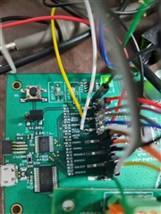
We have the DRV8873SEVM evaluation board for the testing purposes, at first we tested it with the provided GUI app to make sure it works as expected and then we proceeded to remove the resistors to connect it to our board to apply our own tests.
General Info:
- The SPI related pins are connected correctly (SDI, SDO, SCLK, CS).
- Clock speed is configured to 100KHz just like in the sample code.
- SDO is configured as pull-up.
- SPI Mode 0
According to the datasheet both the SDI and SDO consist of 16 viable bits during transactions, SDI's first 8 bits define the operation (R/W) and the register address.
Our first small test was to read the IC1 Control Register who's default data should be 01010001 -> 0x51, correct?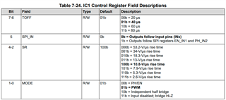
We didn't seem to receive the expected outcome so we've attached an oscilloscope for debugging.
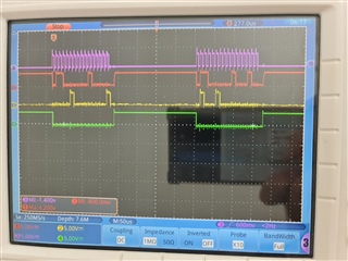
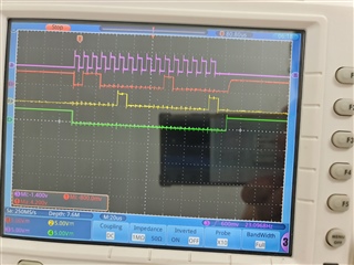
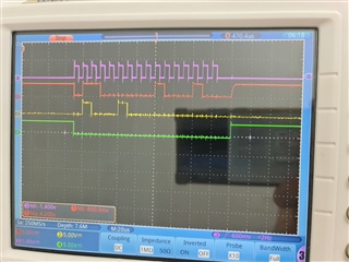
CLK - Purple
SDO - Red
SDI - Yellow
CS - Green
* Attempting to read IC1 Control Register's data, transmitting MSB 01000100 -> 0x44, correct?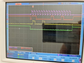
Why was the response not 0x51? Did I do anything wrong?
We figured we might as well attempt a write operation to the same register, transmitting MSB 00000100 -> 0x04, correct?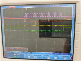
Then we noticed a weird pattern where the DRV8873 is just imitating whatever I'm sending.
Can I get your opinions on this? Am I doing something wrong or is the DRV8873 acting up?