This thread has been locked.

If you have a related question, please click the "Ask a related question" button in the top right corner. The newly created question will be automatically linked to this question.

DRV8316: How to use 3xPWM mode to do sinusoidal (SPWM) control for BLDC motor.

Part Number: DRV8316

Hi All.

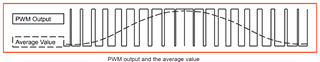
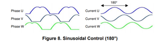
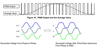
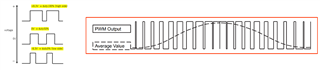
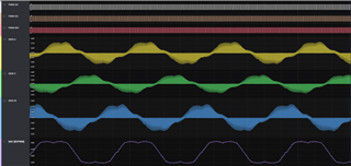
I want to use 3-PWM mode to do sinusoidal (SPWM) control for BLDC motor.
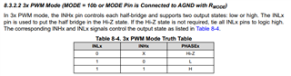
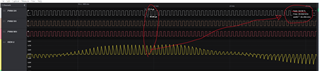
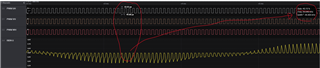
And please tell me how to control INLx and INHx PWM.

Mostly about INLx, when driving the BLDC, all the time INLx is in High level state?

It would be helpful to have a sequence diagram of the six control signals.

  • Hi Kenji,

    One of my coworkers will try to respond to your question tomorrow.

    Regards,

    Anthony 

  • Hi Kenji-san,

    When using 3x-PWM mode with sinusoidal control for this BLDC, the INLx pins are used to control whether or not the corresponding output phases are in Hi-Z (both high side and low side FETs off)  Speaking in logical terms: if an INLx pin is low, that means the FETs of the corresponding phase are in Hi-Z. If an INLx pin is logic high, then the output of the half bridge is controlled with a signal at the INHx pin. In this case, if INHx is low, the low-side FET of the corresponding phase is on, and if INHx is high, the high-side FET of the corresponding phase is on.

    In sinusoidal control, there will always be current flowing through either the high side or low side FETs of each half bridge. This means that there will be no Hi-Z states for sinusoidal operation (note: there will be a brief period of time where both FETs are off when the INHx is toggled from low to high or high to low, but this is simply due to the driver inserting dead time to ensure that both high side and low-side FETs don’t turn on at the same time). There will always be current flowing through each of the phases of the motor.

    Because sinusoidal control does not use Hi-Z states, we can tie the three INLx pins logic high,. This reduces the number of GPIOs from the MCU that are necessary to control the motor. One MCU GPIO will control one half bridge through INHx; a logic low means the low-side is ON and a logic high means the high-side is ON.

    For an in-depth video on sinusoidal control, you can look at the following TI Precision Labs video: https://training.ti.com/ti-precision-labs-motor-drivers-sinusoidal-control

    Regards,

    Johnny

  • Hi Johnny-san

    Thank you for the information!

  • Glad I could help!

  • Hi Johnny-san

    I don't know how controlling the internal FET in 3 x PWM mode.
    So I have a question about SPWM  to control  DRV8316 in 3xPWM mode.

    Please tell me the relationship between sine wave and duty when driving sine wave in 3xPWM mode of DRV8316.

    I could drive BLDC motor with sinusoidal drive in test code.

    My aim in this question is to control the motor by generating SPWM at the command speed rpm,
    set the PWM Duty calculating from speed rpm and kv value.

    Is the relationship between sine wave, Dtuy and prdriver controll is as follows?

    0% < duty≦ 50 %: low side driver control

    duty = 50%: stop (break)

    50%<Duty≦ 100%: high side driver control 

  • Kenji,

    To make sure that the thread question and answer is most useful for everyone, please post this new question as a new thread so that it will be separate from this one. You can use the "Ask a related question" button at the top of the page since it is related to this one.

    Regards,

    -Adam

  • Hello Kenji-san,

    When operating this device in 3x-PWM mode, the following process needs to occur in order to receive a sinusoidal output:

    We need to tie INLx = HIGH and provide INHA, INHB and INHC with MacDonald PWM waveforms 120 degrees out of phase with one another. Macdonald waveforms are PWM-varying profiles that create average sinusoidal voltages on Phase A, B, and C as shown below:

    The Macdonald waveforms create an average value of sinusoidal voltage with third-order harmonics from Phase to GND. These waveforms then get stepped up through the internal gate drivers and at the output, a sinusoidal voltage/current from Phase to Phase is produced.

    Thanks,

    Johnny

  • Hi Johnny-san

    MacDonald PWM that you said is space vector PWM (SVPWM) right? First, I want to do and test simple, basic sinusoidal control with SPWM.

    Does this device not support SPWM? In my test code, DRV8316 works with SPWM.

    In case use SPWM with DRV8316, the relation ship of duty and average voltage is like this or not?
    (I use VM8.3V)

  • Kenji-san,

    I am discussing this question with my team. I will get back to you by the end of tomorrow with an answer.

    best,

    Johnny

  • Kenji-san,

    Yes, this device does support SPWM. The DRV8316 is a Gate Driver and FET integrated device. This device can work on any type of commutation (e.g. SPWM, SVPWM). Yes, the MacDonald waveform PWM is typically used in space vector PWM (SVPWM). 

    The information you sent lacks specification of which phases are being turned on/off. Is this PWM information on the left of the photo that you sent the input gate pulses or the output phase voltage?

    best,

    Johnny

  • Hi Johnny-san

    I referred the SPRABQ3 document, and write some test code. 

    From the relationship between SVPWM duty and current waveform,

    duty > 50%: high side energization
    duty < 50%: low side energization