


Part Number: DRV8432
Hello,
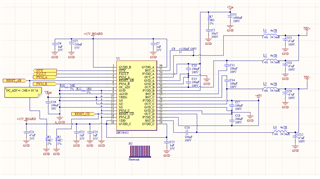
we are trying to use the DRV8432 to drive a TEC and implemented the same circuit as Figure 17 of the datasheet, as reported in the following picture:
We are driving the two PWMs with two opposite square waves of 3.3V at 10KHz. The duty cycle is 50%, we checked both waves with a scope and they are correctly feeded to the driver. Vin is at 48V, because we want to drive a 48V TEC.
The problem is that even when there is no load connected to TEC+ and TEC-, the driver absorbs a significant amount of current (dependend on the PWM switching frequency) and heats up. We also tried with a resistive load of 20ohms, but the behavior is the same.
Regarding the voltage between TEC+ and TEC-, we never managed to reach more than 6V, so maybe there are problems with the turning on of the high side mosfets.
Looking at similar posts we checked the voltage of VREG and BST_x capacitors: VREG is at 3.3V as it should, but BST_A is not at 10V as the others BST. So the component is probably not working anymore and needs to be replaced.
The question is what could have damaged it?
If you notice on the board PVDD_C and PVDD_D are connected to 48V, but there was a design mistake and we tested the driver for a while whitout any voltage applied on those pins. We also tested different PWM frequency, with and whitout the resistive load connected, from 1Hz to 100KHz, always at 50% duty cycle. There may have been some periods in which the control logic didn't work correctly and the device was enabled with DC signals as inputs of the PWMs.
We will try to replace the component soon, but maybe there is something wrong with the schematic or something we missed that caused this problems.
Thanks

