hello team
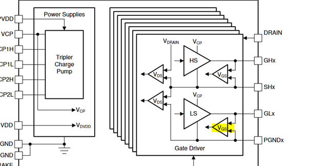
I use the 8718 to control four BDC,but different current on each H-bridge,such as 10A,2A,etc
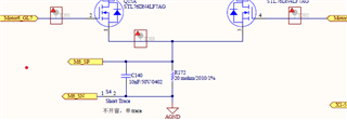
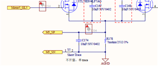
the sample resistors are all connected in low side sense configuration ,how should i connect the PGND1 & PGND from the mosfet to the IC to get a more accuray diagnosis or protection funciton

BTW,what should I take care while driving different load power motors with 8718
The 2rd issue
about the BRAKE function issue,if use with the internal overvoltage monitor
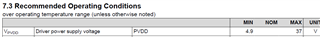
the threshold is around 30V,but the announced OP voltage is close to 37V,how should i understand the acutual operation voltage with normal load driver function