


In some motor driver applications, it is important to monitor and measure the current through the motor. TI has multiple motor drivers with integrated current sensing feature which allows current monitoring through a dedicated IPROPI pin. The IPROPI pin can be connected to an ADC channel of a micro-controller for diagnostics, such as stall detection. The two links below provide more detail about how current sensing works and why integrated current sensing is better than tradition current sensing methods. The purpose of this FAQ is to explain how to configure IPROPI in motor drivers with integrated current sensing and to explain other characteristics of IPROPI.
Configuring IPROPI
The DRV8876 and DRV8874 are motor drivers with the IPROPI integrated current sensing feature. The following configuration procedure uses the DRV8876 and DRV8874 as an example but the general procedure can be applied to most motor drivers with the IPROPI feature.
- Choose the current regulation limit (ITRIP) for your application. The driver will regulate the output current once the current goes above the Note that current regulation is different than over-current protection (OCP) which is a safety feature that will disable the outputs when the current goes above the OCP threshold. Read this FAQ to learn about the differences between these two features. Please see the TI Precision Labs video linked above for help on how to choose the ITRIP limit.
- Determine the IPROPI resistor (RIPROPI) value to properly sense the scaled down output current from IPROPI within the dynamic range of the controller ADC channel. The equation below can be used to determine the RIPROPI value based on the controller ADC max voltage (VADC), ITRIP, and current mirror scaling factor (AIPROPI). It is recommended to choose a resistor with a 1% tolerance for best tradeoff between performance and cost. This equation may not apply for all integrated current sensing devices so make sure to read the device datasheet for detailed instructions on how to choose RIPROPI .
RIPROPI(kΩ) ≤ VADC(V)/(ITRIP(A)*AIPROPI(µA/A))
- Select the VREF value using the equation below. Note the ITRIP is configured with a combination of VREF and RIPROPI. RIPROPI is fixed, however VREF can adjust the ITRIP limit from a DAC or other means. Make sure that VREF≤VADC so that ITRIP stays below the chosen value.
VREF=RIPROPI*(ITRIP*AIPROPI)
Reading current information from IPROPI
The first image below shows a voltage waveform of the output terminal (VOUT) of the motor driver and the voltage at the IPROPI pin (VIPROPI). Based on the VIPROPI measurement, the actual output current can be calculated using the following equation. Again, this equation may differ from device to device, so read the datasheet to learn how to calculate output current.
IOUT=VIPROPI/(RIPROPI*AIPROPI)
The IPROPI pin be connected directly to an ADC channel of a micro-controller to read VIPROPI. Using the equation above, the firmware can respond to the particular current level depending on the required function. Ensure that the ADC sampling rate is appropriate for the desired current sensing application
The IPROPI waveform can be divided into two phases. The driving phase occurs when the H-bridge is in its driving phase. During this phase, the VIPROPI measurement correspond to the current flowing from the drain to source of the power MOSFETs. In some devices, like the DRV8873, the current mirror circuit monitors current in both of the high-side FETs. However, in other devices like the DRV8874 and DRV8876, the current mirror circuit monitors current in both the low side MOSFET and the measurement is only valid when the current flows from drain to source. So, read the device datasheet to understand if the device only monitors current in either both of the high-side or low-side FETs. The decay phase occurs when the H-bridge enters either low-side slow decay, high-side slow decay, or synchronous/asynchronous fast decay (read this app-note to learn more about H-bridge decay). Depending on the decay mode chosen (read the device datasheet to learn about the decay modes supported by the device), current sensing may or may not be possible. If low-side slow decay is chosen, current sensing is possible (only for devices like the DRV8876 and DRV8874 with low-side MOSFET monitoring) since at least one of the low-side FETs will have current flowing from drain to source. If high-side slow decay is chosen, current sensing is only possible for devices like the DRV8873 with high-side MOSFET current monitoring capability. If synchronous/asynchronous fast decay is chosen, current sensing will not be possible during this time since no current will flow from drain to source on either of the two low-side or high-side MOSFETs.
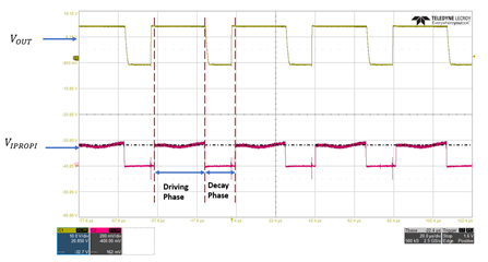
VOUT and VIPROPI waveform for the DRV8876 and DRV8874 (devices with only low-side current monitoring capability)
Other Characteristics of IPROPI
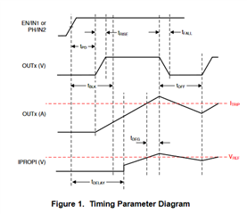
There is a delay from when the input command to enable the output is read by the driver to when IPROPI shows a valid measurement. The diagram below shows this delay which is labeled t_delay. The delay is caused by the signal propagating through the internal components of the current sensing circuitry.
The waveform below shows the IPROPI delay marked by the two vertical cursors. Note that the IPROPI voltage will slew to its final value sometime after the output has been enabled.
The IPROPI signal disables soon after the driver receives the command to disable the outputs. As seen on the oscilloscope image below, the IPROPI signal drops to 0-V soon after IN goes LOW. As shown by the two vertical cursors on the waveform, V_IPROPI is 0-V despite a non-zero motor current. The internal circuit is designed such that the IPROPI output disables when the input pins receive the command to disable the output, rather than when the FETs are fully turned off.

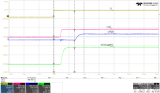
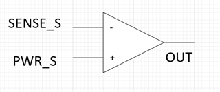
Another important characteristic is that IPROPI signal delay and IPROPI slew rate depend on the power MOSFET ON resistance (RDSon) and output current (IOUT). There is an internal amplifier at the end of the IPROPI circuit which compares the voltage of the source of the power MOSFET (PWR_S) of the H-bridge and the source of the current mirror FET (SENSE_S). Below is a simplified schematic of the amplifier. SENSE_S = VM – I_PROP*R_sensefet where I_PROPI is the current through the sense FET and R_sensefet is the ON resistance of the sense FET. Similarly, PWR_S = VM - I_mot*R_pwrfet, where I_mot is the motor current through the power MOSFET and R_pwrfet is the ON resistance of the power MOSFET. If the voltage difference between the positive and negative terminals of the amplifier (V_dif = PWR_S - SENSE_S) is low, the amplifier output will take longer to reach its final value. On the other hand, when V_dif is high, the amplifier output will take less time to reach its final value. So, if the motor voltage is low or the On resistance of the power MOSFET is low, the IPROPI delay and slew rate will be higher. Below is a waveform showing examples of both low and high motor currents using the DRV8873. Note that the ON resistance of the FET is the same in both cases but the motor current is adjusted. You can observe that the IPROPI delay and slew rate is much larger when the motor current is lower.
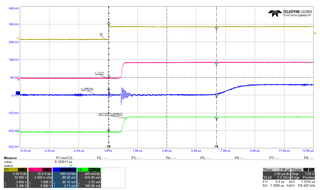
60Ω Load (CH1: IN, CH2: Motor voltage, CH3: IPROPI, CH4: Motor current)

10Ω Load (CH1: IN, CH2: Motor voltage, CH3: IPROPI, CH4: Motor current)
