This thread has been locked.

If you have a related question, please click the "Ask a related question" button in the top right corner. The newly created question will be automatically linked to this question.

DRV8256: DRV8256EPWPR fast decay PWM?

Part Number: DRV8256

Hi teams:

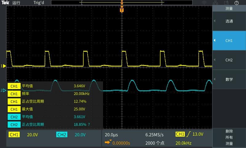
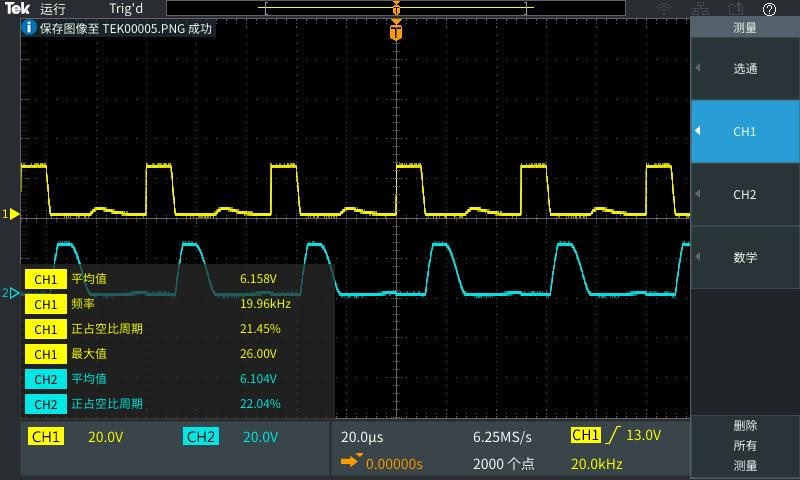
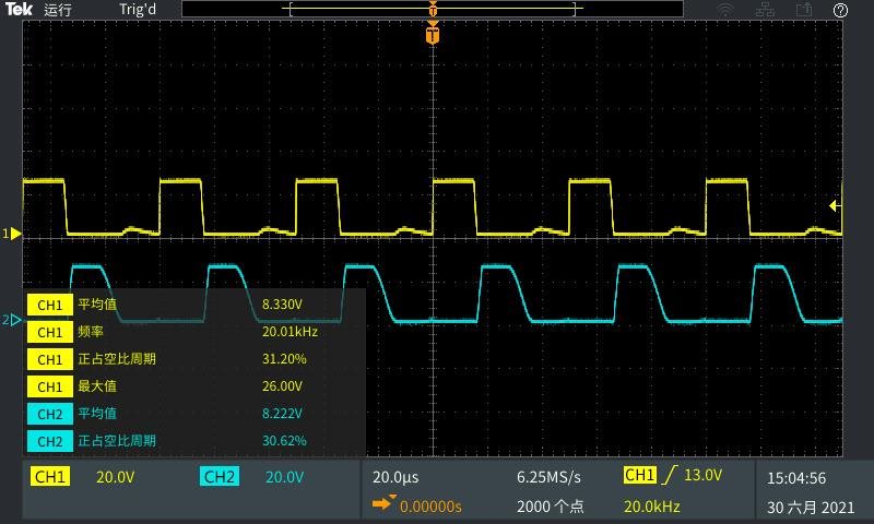
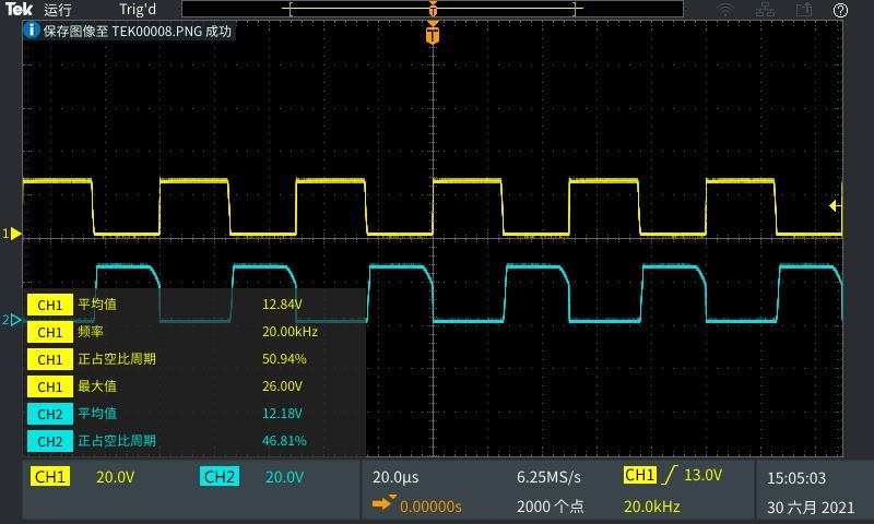
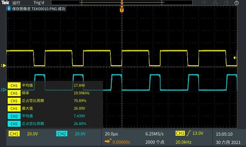
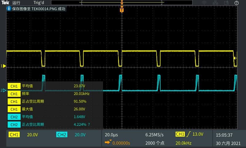
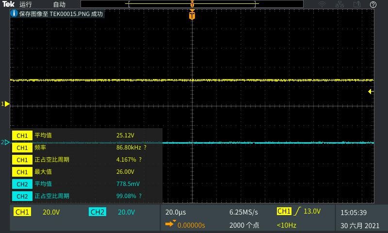
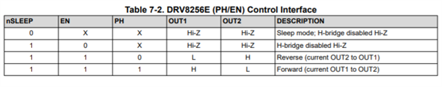
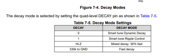
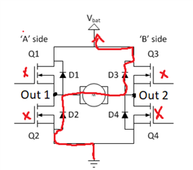
When the 8256e is set in the fast decay mode, is there any output only when the input PWM duty cycle is within 50% - 100%?

  • Hello Kevin,

     As long as your VM is within the recommended voltage (4.5 to 48V), and your logic inputs are hooked up properly, you should be getting an output regardless if it is below 50% duty cycle. There might be a situation in which if you lower your duty cycle you would get no output. That is if the duty cycle is only sending a signal less often than the propagation delay (800ns) and the rise time (dependent on the motor you are using). This table from the data sheet might be helpful:

    I hope this answered your question!

    If not, and instead you are trying to troubleshoot something please let me know:

    Are you having issues driving the motor when the duty cycle is below 50%? If so could you tell me a little bit more about how you have it set it up, which motor you are using, and how you are controlling it.

    Regards,

    Pedro Arango Ramirez

  • The load is DC 20V drive motor, and the setting conditions are as follows: VM: 24 V DC nsleep: 1 pH: 1 en: PWM input frequency: 20 kHz toff: 16 µ When the PWM duty cycle of en input is less than 50%, there is no voltage at both ends of the motor. The waveforms of out1 and out2 with input pwm1 0% - 100% are attached below.

  • DRV8256EPWPR

    VM:24 V DC,nsleep:1,pH:1 EN:PWM输入频率:20 kHz toff:16µS。

    The customer wants to confirm: adjust the speed by adjusting the duty cycle of input en?

    Which parameters are related to the adjustment speed.

  • Hello Kevin, 

    Thank you for following up.

    You are correct, to modulate the speed you should adjust the duty cycle of input EN, more information below. 

    The following table explains the functionality of the control modes:

    If PH is left on 1, and you PWM EN then the system will switch between forward and coast mode. Therefore if you want to have the forward mode engaged for longer you would increase the duty cycle driving EN. This would cause the motor to spin faster, if you wanted to slow down you would lower the duty cycle. 

    I hope this answered this part of the question. Let me know if there is need of clarification. 

    Best,

    Pedro Arango Ramirez

  • Hello Kevin,

    Thank you for the response. This behavior is not what I would expect to happen with the signals in the described usage. If the CH1 is measuring the voltage drop between OUT1 and ground; while CH2 is measuring the voltage drop between OUT2 and ground then the following table would explain what should be showing for CH1 and CH2. 

    In an H Bridge set-up  Hi-Z should be reading as low. Meaning that when you regulate the voltage We should see OUT1 oscillated as the PWM oscillates and OUT2 should be constantly low. Essentially switching between Line 2 and Line 4 of the table above.

    The fact that at high duty cycles OUT1 and OUT2 are opposite to each other makes me believe that the system is actually switching between Forward and Backwards, meaning Line 3 and Line 4 of the table. This would be in line with what we see on the reading from the oscilloscope images you uploaded.

    Additionally the inclusion of a time off makes me believe that there might be some PWM current chopping happening. When the current exceeds the I-trip value current regulation goes into place overriding the control interface until the current decays below I trip. This is described in detail in pages 14, 15 and 16 of the data sheet. Current regulation might be the culprit of this unexpected behavior. 

    Therefore I would like to ask you some questions to better be able to assist you:

    Would you be able to send me a schematic of how the driver was wired up to the motor?

    Would you be able to confirm that DRV8256e is in use rather than DRV9256p?

    Would you be able to confirm if the waveforms above were done with the motor loaded or unloaded, if they were done with the motor loaded would you be able to repeat these readings with it unloaded?

    Answers to these would be really helpful diagnosing the problem. In the meantime I will perform some tests in the lab to compare waveforms and investigate if perhaps the Driver in use is faulty. If you have any questions in the meantime please do not hesitate to reply. 

    Best regards and thank you for your collaboration, 

    Pedro Arango Ramirez

  • Pedro Arango Ramirez:

    1. DRV8256e.

  • Hi Pedro:

    I am sure I am using DRV8256E. The above waveform is generated when the motor is under no load. The schematic diagram is as follows:

    I set the fast decay mode. Is the oscilloscope waveform correct? 

    If I see that OUT1 oscillates with the PWM oscillation, but OUT2 is always at low level, is it slow decay mode? But DRV8256E does not have this mode.

    Looking forward to your reply!

    Li

  • hi Pedro :

  • Hello Li ZiJie,

    Thank you for your detailed response, the schematic was very helpful and I believe it has helped me found an explanation to the problem. 

    Something I would like to clarify is that in the current setup where Ph=1 and EN=PWM you are not switching from Drive to fast decay. By doing so you are going from Drive to Coast. 

    When you state that you have set up the device for fast decay you are referring to putting a 330ohm resistor to ground according to this table:

    However this will only happen if the current regulation threshold is reached. When the current reaches I-trip, the outputs will no longer follow the PWM inputs to pin E1. Meaning that as long as the current regulation is not tripped, the device will not be in fast decay mode but rather follow the input as stated in the following control table:

    With PH=1 and EN=PWM this would switch from Drive to Coast as I stated above. However this is not an undesirable setup, as it will allow you to drive the motor at full throttle. 

    Knowing that the motor is actually in Drive to Coast modes the waveforms you sent me are perfectly in line with what I would expect to see and the device is working as intended. This is due to how voltage is measured during Hi-Z operation. 

    Regarding the issue with the motor not outputting anything when the duty cycle is below 50%:

    After doing some testing I have come to the conclusion that below 50% there is simply not enough current to provide the necessary torque to spin the motor. This is to say that the duty cycle at which the motor will begin to spin will vary from motor to motor and is specific to the internal components of the motor. 

    Please let me know if you have any other questions and thank you again for your detailed communication.

    Best,

    Pedro Arango Ramirez. 

  • Hello Pedro:

    If the motor is actually in Drive to Coast mode, can you explain in detail how the voltage waveform of OUT2 to ground is generated?

    Best regards

    Li

  • Hello Li,

    Thank you for your question, I will be glad to provide information by end of day tomorrow 7/6/2021 as today it is a national holiday in the US. 

    Best regards,

    Pedro Arango Ramirez

  • Hello Li,

    I m back and I will gladly explain how it works. In order to understand why the voltage in OUT2 is basically out of phase with the voltage in OUT1, and why it drops to zero before the next cycle in low duty cycles we need to understand how an H bridge works in its different states; specifically the drive state and the coasting state. 

    When the motor is in the drive state the Q1 and Q4 gates open allowing current to flow through the windings of the motor as follows:

    The windings can be thought as an inductor which has the property of maintaining current . This will make it such that when the motor is driving OUT1 will be high will OUT2 will be low. However during coasting mode we enter into the Hi-Z space. In coasting all gates Q1,Q2,Q3, and Q4 will be closed, therefore current will flow through the flywheel diodes or body diodes of the MOSFET as follows:

    Current continues to flow through the inductor as the magnetic field created by it diminishes. 

    Because current is flowing through the diodes it acts as a closed circuit, as soon as current stops, the diodes will begin to act like an open circuit. For explanation purposes we will assume the diodes are perfect and minimal voltage is dropped across them. As long as current is conducting, Out2 will be in the same node as Vbat, while Out1 will be in the same node as ground. 

    At lower duty cycles the current will decay quicker, making it such that D3 and D2 act as an open circuit bringing both of the voltages of Out 1 and Out 2 back to zero. 

    I hope this was helpful in order to understand the waveform in coasting mode. Please let me know if you have any other questions.

    Best,

    Pedro Arango Ramirez.