This thread has been locked.

If you have a related question, please click the "Ask a related question" button in the top right corner. The newly created question will be automatically linked to this question.

DRV8353R: Current sense offset

Part Number: DRV8353R
Other Parts Discussed in Thread: TMS320F280049, DRV8353

I am seeing a higher than expected offset error from the current sense amp outputs.  With VRef = 3.306V, gain set to 40V/V, SOA = 1.635, SOB = 1.664 and SOC = 1.638.  I can rerun the auto-calibration but always end up with similar results.  

This is on a custom PCB connected to the analog inputs (A3, B3 and C4) of a TMS320F280049 microcontroller.  Things work but I am trying to track down a fairly significant current sense error.  I am measuring these offsets in firmware and subtracting from the measured currents but since this doesn't appear to meet the datasheet specification of +- 3mV I thought I should look into it.  

Any thoughts appreciated.

Thanks

Don

  • Hi Don,

    Just to check it out, can we take a look at your PCB schematic?

    Thanks,

    Matt

  • Don,

    Thanks for the additional info. We'll get a response to you by the end of tomorrow.

    Best,

    Johnny

  • Hello Don,

    The following are the potential issues we have found:

    • The resistor attached at your IA, IB, and IC outputs is too small. This resistor should be in the 1kOhm range. You might be overloading the output of the sense amplifier with current here.
    • If you are using a common ground pour rather than a kelvin connection for your 3mOhm shunt resistor/SNx nodes, this could also cause problems related to the offset you are seeing.

    Best,

    Johnny

  • Thanks for the response.  I have a kelvin connection to the current sense resistors, also the offset is present when there is no current through the bridge as well as when the DRV8353 is in manual calibration mode.  A 1k series resistor is too high to drive the A2D in the TMS320F289949 processor (50 ohm, table 5-44).  I can try a smaller capacitor/larger resistor but I would expect this to show up as an oscillation and not a stable DC offset.  The evaluation board for this chip uses 56ohm and 2200nF.

  • Don,

    I'll get a response to you on Tuesday, after the holiday.

    An important note: the EVM board for this chip uses 2200pF caps at the headers.

    Best,

    Johnny

  • Hi Don,

    Please take note that July 5 is the Independence Day holiday in the US.

    The team is out of office and will get back to you as soon as they return!

    Thanks,

    Matt

  • No problem.  I'll be back in the office on July 6 and can try a smaller capacitor. Not much else to do if there are no design mistakes.  

  • Don,


    I would recommend testing the offset using the values on the EVM for the SOx output filters so we can eliminate the possibility of the filter values being the issue. The prior value I gave in the 1kOhms range was not correct, which was my mistake. If you have your series resistor value above ~50 Ohms, you should be in a good range to eliminate the possibility of error here.


    On a separate note, can you take a screenshot of SOx during switching in order to observe its transient performance? Since your capacitor is quite a bit larger than the EVM's, a worthy concern is that SOx needs to source quite a bit of current (for a lengthy amount of time) in order to charge up.


    Would you be able to set the CSA_CAL_X bits to 1 and test the SOx outputs? When CSA_CAL_X = 1 the corresponding amplifier inputs are grounded to calibrate the offset. It would be good to know if the offset is accurate while CSA_CAL_X is set to 1.


    It may be worth it to measure SOx to ground with a DMM to eliminate the possibility of the problem being with error being introduced with the ADCs on the MCU.


    Are you turning on any MOSFETs when performing the test to check the offset? If so, which ones? Do you have any other devices with which you've seen similar behavior when doing this test?


    best,
    Johnny

  • I have not had a chance to collect this information, I'll try to respond in a day or two.  All measurements I have sent are measured with a DMM. All bridge MOSFETs are off.  I have two boards, offset is similar on both.  

    Thanks

  • I changed the filter components to 56 ohms and 2200pF.  The DC offset remains basically the same.  I'm also not seeing a measurable difference when in manual calibration mode.  

    VRef=3.307

    After requesting an auto offset cal via SPI and pausing the processor at a debug breakpoint the offset measure with a DMM:

    SOA = 1.640

    SOB = 1.688

    SOC = 1.639

    Putting the device in manual calibration mode and again pausing the processer the offset measure:

    SOA = 1.640

    SOB = 1.689

    SOC = 1.639

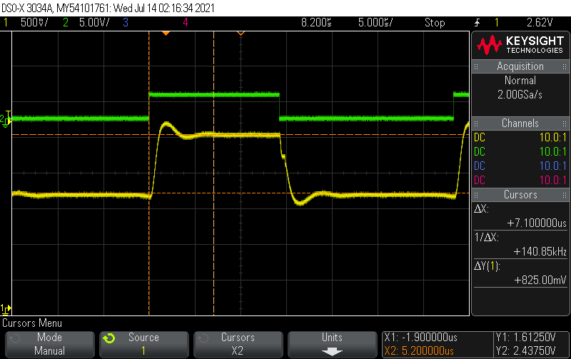
    The yellow trace in the plot below is SOC, green trace is INL_C.   

    I took a second board and removed the low pass filter components so the current sense amp outputs are not loaded at all and measured the offsets.

    VRef=3.287

    After requesting an auto offset cal via SPI and pausing the processor at a debug breakpoint the offset measure with a DMM:

    SOA = 1.628

    SOB = 1.697

    SOC = 1.676

    Putting the device in manual calibration mode and again pausing the processer the offset measure:

    SOA = 1.628

    SOB = 1.696

    SOC = 1.676

    Thanks

  • Don,


    Can you perform the following basic test: power up just the device, then pull the enable pin high, while not applying any voltage to the INx pins, and then test SOx outputs with a DMM while supplying VREF. If SOx outputs still have the offset error, then you could short the sense resistor to ensure 0V across SPx - SNx. If the issue still persists, this would indicate a possible trimming issue.


    best,
    Johnny

  • With the exception of shorting the current sense resistors, this is no different than what I have been doing all along.  I do not apply voltage to the INx pins before or during offset calibration.  The GPIO pins are configured and set to 0 before setting the enable pin high.

    I shorted the current sense resistors, R4,10 and 2, on my second board and measured the offsets below.

    VRef=3.285

    SOA = 1.626

    SOB = 1.696

    SOC = 1.674

      Thanks

  • Don,

    I've re-reviewed this thread, and I have noticed a possible misunderstanding that I need to clarify. The datasheet spec you mentioned in your initial question of offset error being +-3 mV: This is the input-referred offset error, not the output-referred error.

    You are measuring SOx, which is the current sense output. The offset error of this output will have a margin which depends upon what gain setting you are using. The output offset error would be the input offset error multiplied by your amplifier gain setting. In your case (Amplifier Gain = 40 V/V), your output offset error would be +-3mV * 40 = +-120mV. The numbers you are receiving fall within the existing margin, given your gain setting.

    I apologize for the misunderstanding. If you would like to reduce this offset, you would have to reduce your gain setting. Reducing your gain will lead to a smaller signal on the current sense output, unless you increase your shunt resistor value accordingly.

    best,

    Johnny.

  • Hum, guess I missed that as well.  Is the drift also referred to the input of the amplifier stage?  

  • Don,

    Yes, This would be the case.

    Make sure to let us know if you have any other questions.

    best,

    Johnny