


Hi experts,
I'm a little confused about the operation principle of DRV2510-Q1. Could you pleas help on below quesitons?
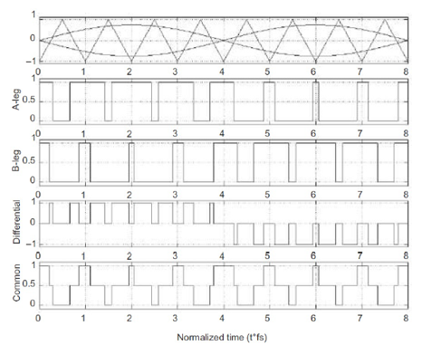
1. About BD modulation. From my understanding, the BD modulation is working as below picture shows, the input sinewave and its reserve waveform are compared with a triangular wave and then get the PWM control signal to the internal H-bridge MOSFET. But the input of DRV2510-Q1 is PWM, so could you please let me know how DRV2510-Q1 implement the BD modulation?
2. Could you please give some explanation about the relationship between input PWM and output PWM?
1) If input is in single-end mode
My understanding is the output PWM duty ratio is the same as the input PWM signal, but the output PWM frequency is determined by freq_sel, is it right?
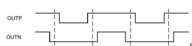
2) If input is in differential mode
What's the IN+ and IN- signal requirement? For example, if I want below output PWM, what signal should be added at IN+ and IN- respectively?
3. Shoud customer add LC filter at OUT+ and OUT- like class D audio amplifier? It seems the LC filter is optional.
Arie
