Hello.
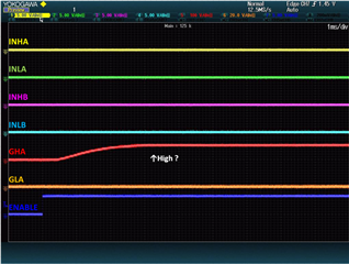
It sets the PWM mode to the 6 xPWMs mode at present. It becomes a high without GHA, GHB and GHC becoming Low when inputting 0 to all INL and INH terminal and making ENABLE High from Low because we want to make all FETes an off condition at starting-up of a software. A attachment image is the INHA, INLA, INHB, INLB, GHA, GLA and ENABLE signal from above. High is output like GHA about GHB, GHC, too. Is the IC out of order?