This thread has been locked.

If you have a related question, please click the "Ask a related question" button in the top right corner. The newly created question will be automatically linked to this question.

DRV8316: Operating issue & pin setting review

Part Number: DRV8316

Hi,

The customer is testing using DRV8316.

The motor is not operating properly.

1) Is there any part of the environment that set wrong?

2) Please give me a guide to the minimum setting required to drive the motor.

Pin Setting

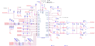
- nSLEEP : HIGH (5V), DRVOFF : LOW(0V), SPI settings (STATUS registers, CONTROL registers all initialize to data bit 0)

Output Voltage By Pin

-VREF : 3.3V, SOA, SOB, SOC : 3.24V, VM1~3 : 12.2V, Cp : 17.2V, AVDD : 3.3V, FB_BK : 3.27V, CPH : 12.2V

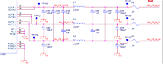
- INHA, INHB, INHC: Input PWM values according to motor pin map

- INLA, INLB, INLC: Input GPIO values according to motor pin map (HIGH, LOW)

  • Hi Cho,

    Few questions:

    1) How is motor operating? Is it not spinning, vibrating, etc.?

    2) What algorithm is customer using to spin motor? Trapezoidal? Sinusoidal? FOC? Can you elaborate on "motor pin map"? Are PWM values given to INHx/INLx inverting or is INLx kept low while INHx PWMs are given?

    3) Do the SPI settings work correctly (write/read)? Can you share register settings?

    I will review schematic and leave feedback by EoD. Can you try these settings?

    SLEW = 200V/us (3b), GAIN = 0.15V/A (0b), MODE = 6x PWM (0b), EN_ASR = 0b, EN_AAR = 0b

    Thanks,
    Aaron

  • Hi Aaron,

    Q1) Motor is not running (motor driver nFAULT = 0V)

    Q2) Sinusoidal, attachment for motor pin map, When PWM is entered in INHx, INLx is Low (0V).

    Delete file

    Q3) SPI write/read is normal.

    IC_Status : 1000 0000 0000 0000

    Status__1 : 1000 0010 0000 0000

    Status__2 : 1000 0100 0000 0000

    Control__1 : 0110 0000 0000 0000

    Control__2 : 0000 1000 0001 1000

    Control__3 : 0000 1010 0000 0000

    Control__4 : 0000 1101 0011 1111

    Control__5 : 0000 1110 0000 0000

    Control__6 : 0001 0000 0000 0010

    Control__10 : 0001 1000 0000 0000


  • Additional

    Connected to the motor,

    INHA : 0%(PWM), INLA : HIGH(5V)

    INHB : 25%(PWM), INLB : LOW(0V)

    INHC : 0%(PWM), INLC : HIGH(5V)

    The OUTA/OUTB/OUTC value is output momentarily and nFAULT is low.

    Blue(2) : nFAULT, Yellow(1) : OUTA(U), Purple(3) : OUTB(V), Green(4) : OUTC(W)

  • Hi Cho,

    Attached review of schematic here: drv8316_sch_review.pdf

    Is the motor connected to RH_FR_OUTx or after the fuses at RH_FR_M_x? What is the purpose of the added 2.2uH inductors, phase to phase capacitances, and phase to GND capacitances before and after the inductor? Is this supposed to just be filtering? We would not expect any components at the OUTx pins of the device that add extra impedance and inductance to the motor, or else this can make commutating the motor sinusoidally much more difficult. 

    From the waveform above, looks like all outputs are trying to go high simulatenously when INHB = 25% and both INLA and INLC = on. For sinusoidal commutation, I would expect all three phases to have a duty cycle with synchronous PWM waveforms to avoid current recirculation through the LS body diode, or else this can produce higher switching losses. Another resource for sinusoidal control is here: https://www.youtube.com/watch?v=-By_vt27Xhs

    Could you try removing the inductances and capacitances on the motor outputs and consider running synchronous PWM waveforms for commutation rather than asynchronous, or consider using 3x PWM mode so that INLx can be kept at a 1 while feeding the INHx signals?

    If the buck is unused, can this be disabled through BUCK_DIS bit?

    Thanks,
    Aaron