This thread has been locked.

If you have a related question, please click the "Ask a related question" button in the top right corner. The newly created question will be automatically linked to this question.

DRV8805: Need help with smoothing out motor driver step resolution and rotation direction

Part Number: DRV8805

Hello,

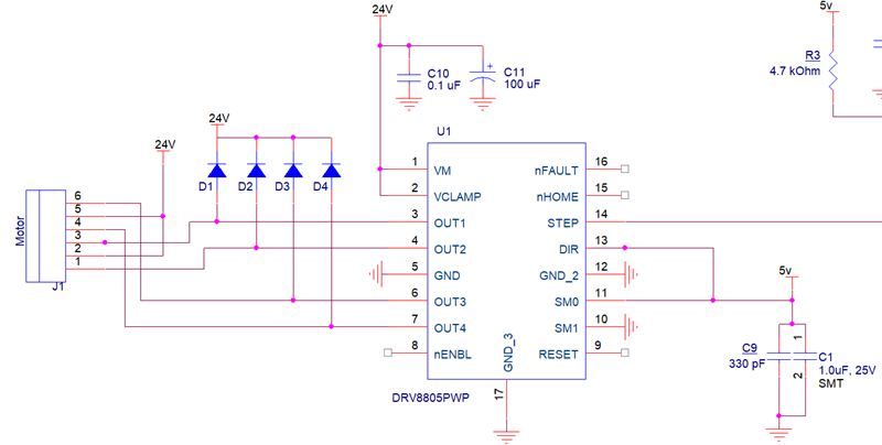
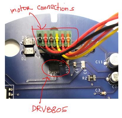
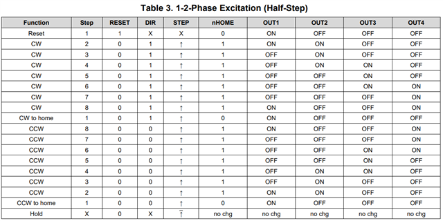
I have a DRV8805 chip driving an NPM PF35T-48B1 motor. It seems that when the motor goes thru a rotation, the steps look jerky and seems like the resolution should be improved so the rotations become smooth. Also, I'm supplying 5V on the DIR pin which should make the motor rotate clockwise but when I apply power, a lot of the time the motor turns counter clockwise. My questions are:

1. How can I smooth out the rotations?

2. How to I make the motor turn clockwise consistently?

I attached a video I hope you can view. The left unit is the one being driven by the TI DRV8805 chip.

Thanks,

Jose

Click here to play this video

  • Jose,

    1. How can I smooth out the rotations?

    Would you try half step operating to see if it is smooth than before?

    2. How to I make the motor turn clockwise consistently?

    Does the motor terminal wire have the color code? When you connect the motor to DRV8805 output, can you make sure the same color wire is connected to the same DRV8805 every time?

    Regards,

    Wang 

  • Hi Wang, 

    I have the DRV8805 set to half-step currently already. Here is the schematic for how I have connected the DRV8805 to the motor. I have this on a prototype board so the traces are set. The DRV8805 chip output is connected to the motor the whole time. 

    Not sure if the previous video I sent was visible but that second rotating unit was just there for reference of a smoother rotation although I'm not sure its apparent from looking at it.

  • Jose,

    The video is not visible. I want to double confirm:

    The DRV8805 chip output is connected to the motor the whole time. But, with 5V on DIR, some time the motor rotate clockwise; a lot of the time the motor turns counter clockwise.

    Is the motor rotation speed and noise similar in both direction? I would like to see that video to understand it?

    Regards,

    Wang

  • Wang, 

    Yes the DRV8805 chip output is connected to the motor the whole time. And yes, when I power up the circuit the motor rotates clockwise some of the time and counter clockwise a lot of the time. The motor rotation speed looks similar in both directions and there really isn't any noise.

    I have uploaded the video to WeTransfer and also to Dropbox incase the first link doesn't work, here there are below:

    https://we.tl/t-K5IHJsM32f (WeTransfer link)

    https://www.dropbox.com/s/efno7gw1d5nrwfm/1927_no_light.MOV?dl=0 (Dropbox link)

    Let me know if these help you understand or if I need to take another video.

    Thanks,
    Jose

  • Jose,

    For the spinning direction, we have to check the output following the table 3 or not. Please step by step send single STEP plus to STEP pin. The output should follow table 3 and run into one direction unless the DIR pin voltage is changed.

    I saw the video from the dropbox link. It is OK to me and the two motor spinning directions are same. If you want to more smooth, you may have to use "Wave Drive" option to control the output current and get a high resolution. It seems complicate because the host controller needs to control the current regulation point step by step.

    Regards,

    Wang Li

  • Wang, 

    Once power is applied to the circuit, the motor spins in a certain direction and does not change direction as long as power stays on. So this tells me that the chip is outputting correctly following the table 3 steps. Am I right in thinking this?

    Once power is turned off and re-applied, the direction the motor spins in is not predictable. So I think the issue lies during initial power up where it seems to be confused on the DIR pin input and which direction to start rotating.

    Here is a dropbox link to another video: https://www.dropbox.com/s/igr3f7o5teirj9l/cw_ccw_rotations.MOV?dl=0

    When I first apply power, it spins CCW but when I remove power and reapply, it starts spinning CW. I have 5V on the DIR pin the whole time so it should always be spinning CW. Any thoughts on how to fix this?

    Thanks,

    Jose

  • Joes,

    " So this tells me that the chip is outputting correctly following the table 3 steps. Am I right in thinking this?" I agree with you.

    Would you change the DIR setting during the motor spinning? Does the motor spinning direction change? After DIR setting change, do you see  the motor speed change?

    If the motor direction can be changed after DIR setting change and the output following the table 3, we should not see any problem.

    If the motor direction keeps same after DIR setting change, but the motor speed is different. I would think we may need to slow the motor before change the DIR setting.

    If the motor direction keeps same after DIR setting change and the motor speed is same as before, I would think we need to control DIR signal and nSLEEP signal startup sequence to make DIR voltage is stable before nSLEEP pin voltage goes high.

    Regards,

    Wang Li

  • Ok I will try that. The DIR input trace is etched into the board so I will try to cut it and solder a wire so I can alter the DIR setting while it is spinning.

  • Jose,

    Thank you for helping the verification and debugging.

    Regards,

    Wang Li

  • Wang,

    So I cut the trace connecting the DIR pin to 5V and my results are in the video links below.

    In the first video, I have the DIR pin not connected to 5V so the DIR input should be at 0 looking at the internal pull-down resistor and should spin CCW however when I apply power I still get the same result. Sometimes it spins CW and sometimes it is CCW during initial power up.

    In the second video, I kept the motor spinning and left power connected but altered the DIR input by connecting and disconnecting the blue wire (DIR pin). Sometimes the spin direction changes and sometimes it doesn't. The rotation speeds seem to be similar.

    video 1 -- https://www.dropbox.com/s/mkjfmu37wlueh3g/video1_DIR_pin_not_connected.MOV?dl=0

    video 2 -- https://www.dropbox.com/s/qv7bgb8se47yl3e/video2_altering_DIR_input_while_spinning.MOV?dl=0

    Regards,

    Jose

  • Jose,

    I cannot understand this DIR behave. Is it a soldering issue? Would you replace the DRV8805 and retry it?

    Regards,

    Wang Li

  • Hi,

    Motor connection might be wrong, please take a look at post below. It looks like motor is connected according to first diagram.

    https://e2e.ti.com/support/motor-drivers-group/motor-drivers/f/motor-drivers-forum/550281/drv8805-excitation-procedure

    Regards,

    Grzegorz

  • That fixed it!! The rotation looks a lot smoother now too. Thanks so much!!

  • Grzegorz,

    Thanks,

    Wang Li

  • I am glad to hear the problem was solved.

    Regards,

    Grzegorz