This thread has been locked.

If you have a related question, please click the "Ask a related question" button in the top right corner. The newly created question will be automatically linked to this question.

DRV110: Solenoid Driver Design. The Holding current will not increase much.

Part Number: DRV110

Hi Team,

We would like to ask your help regarding the customer's inquiry below regarding DRV110AQPWRQ1.

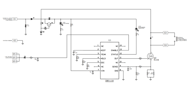
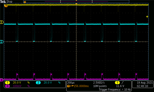
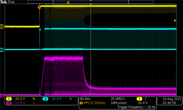
Driving a heavy solenoid for a new industrial contactor rated at 11 Ohms and 141 MilliHenry Inductance.  Using the T.I. Evaluation (EVM) module for testing, that module will not adjust the Holding current very much.  On the T.I. Evaluation module, we changed the shunt resistor from 1.0 Ohms to 0.5 Ohms.  Copied this same change to our prototype circuit board.  Set the EVM C3 capacitor to 1µF and that does produce our 0.1 Second "Keep" time just fine.  Adjusting the "Peak" resistor to 78 KOhms, our peak value of 1.5 Amperes comes in just fine.  Our heavy solenoid pulls in just fine.  Our Holding current, as measured on the 36 Volt power supply reads 40 Milliamperes or much too low.  We want nearly three times this value.  Adjusting the "Hold" resistor up and down, we can reach 70 Milliamperes but no higher with numerous resistor value changes.  While the power supply reads 40 Milliamperes, the peak volts across the 0.5 Ohm shunt resistor reads 0.125 Volts with a 10% duty cycle or 0.25 amperes.  We are using the R7 & C1 low-pass filter on our prototype, same as the EVM module uses.  We have tried various shunt values from 0.2 Ohms to 0.41 Ohms also but not a 1.0 Ohm.  BTW, we use a separate and fixed 12 VDC supply for the EVM and prototype units.  We cannot program the Holding current to achieve a higher value even on the EVM module.  According to the T.I. Drive Parameter program, we should be in a working range for the shunt.  

Thank you for your support!

Regards,

Danilo

  • Hi Danilo,

    Does your protoype circuit board function as intended or is it only EVM causing the problem?

    Could you share details to your schematic and calculations using DRV110 calculator tool?

    Thanks,
    Kevin

  • Hi Kevin,

    Here is the schematic diagram and waveform of frequency and peak current from our customer.

    Hold Operating Frequency

    36VDC with 1.6A Peak Amperes

    Regards,

    Danilo

  • Hi Team,

    We have received this feedback from our customer,

    I am writing here to let you know what I am finding.  

    On the T.I. Evaluation module and our prototype module, the responses were the same.  The “Keep” time is good, the “Peak” current is good, but, the “Hold” current would not increase to where we needed it to be.  We have spent a LOT of time trying to solve this problem without success.  Next, we started to think outside of the box and that led us to the “Sense” feedback and filter.  We used (and did not change) the default values of R7 and C1 devices on the T.I. EVM module.  Thinking, possibly, as a feedback mechanism closed loop, we should look here.  We do have a typical inductive spike on our large contactor coil upon release of each PWM pulse.  We started to change the values of R7 and C1 to much higher values, approximately 10 times their default values.  Well… the “Holding” current jumped up significantly and the pulse width widened (and cleaner) into the area where we need to be, nearing ¼ Ampere, RMS.  

    There seems to be very little information regarding this low-pass filter and how to handle it in the literature.  This appears to be the factor that was overriding our programming resistors and has a huge influence on the DRV110 programming.  

    Being I cannot respond to the E2E page directly, I am hoping you can forward this information to your other technical people to let them know how I “think” I solved the problem so we can all learn how to better program this device.

    It would be nice to hear your thoughts.

    Regards,

    Danilo

  • Hi Danilo/Customer,

    Good to know that you have converted your application of DRV110 into acceptable performance.

    Please allow me to provide additional feedback to this matter by EOW.

    Thanks,

    Kevin

  • Hi Kevin,

    Looking forward to your feedback.

    Regards,

    Danilo

  • Hi Kevin,

    May we ask for an update to our customer's inquiry.

    Regards,

    Danilo

  • Danilo,

    Please refer to my feedback on this issue below:

    Since the current is controlled based on a SENSE pin voltage comparison with an internal reference voltage, high noise environments are likely to negatively impact your system. Increasing sense resistor value, hold/peak current component values, etc. TI LPF values recommended in the literature are for a typical situation/implementation and TI does not guarantee those values will work for your system.

    The fact of the matter is each application requires a slightly different approach. I am glad that your team was able to troubleshoot this issue internally, and I hope to share your feedback across other application troubleshooting efforts. I appreciate your inputs to this matter and I do apologize for the delay.

    Thanks,
    Kevin