This thread has been locked.

If you have a related question, please click the "Ask a related question" button in the top right corner. The newly created question will be automatically linked to this question.

DRV8353R: Variation in gate rise times

Part Number: DRV8353R
Other Parts Discussed in Thread: DRV8353

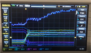
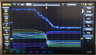
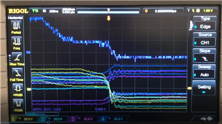
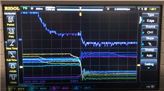
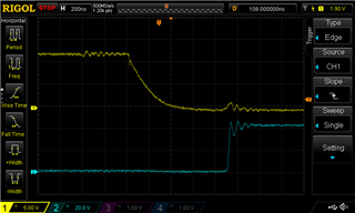
I am running the DRV8353 and measuring the gate-source difference. There is a significant variation in the rise time that shouldn't exist. Some examples are below (Blue is gate, yellow is source, purple is gate -source):

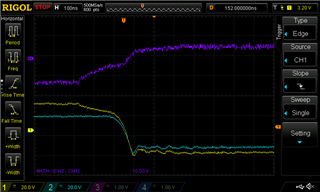
This is over the same MOSFET and constant load so it would be expected the wave forms to be very similar.

I have tried this with an IDRIVE of 300/600mA and 450/900mA and the variation occurs in both.

The schematic for a single phase is as below:

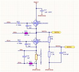
Is there a reason that this variation would occur and how could I eliminate it? The hardware chip is being used and is configured to be 6x PWM, 10V/V gain and 0.2V Overcurrent trip voltage.

Thanks,

Oliver

  • Hey Oliver,

    It seems like screenshot #2 seems to be nominal turn off of the FET, while screenshot 1 and 3 are abnormal. What changes did you make between these screenshots?

    The FETS you're using have a nominal Qgd of 34nC, while using a IDRIVE setting of 300mA, the resulting rise time is 113ns (actually it's a little bit slower because of your series gate resistor, if you let me know your VBAT voltage, I could tell you exactly what the IDRIVE strength is). As a general rule of thumb we ask customers to design their system such that their rise and fall time is between 100ns-200ns. Rise time can be calculated with the following equation:

    Risetime = Qdg/IDRIVE strength

    Just as a test, can you try lowering your sink and source current to 200mA/300mA

    Thanks,

    Michael

  • Hi Michael,

    There were no changes between screenshots 1-3. I was running a motor at constant load and just pressing the single capture on the scope. I am planning on doing a capture of a number of consecutive waveforms to see the frequency of good vs abnormal waveforms.

    VBAT is 48V but could drop to as low as 38V.

    I'm on the hardware device so will have to do 150/300mA bu I'll get that test done today too.

    Thanks

  • Hi Michael,

    I have done some testing with IDRIVE at 150/300mA. This has a big impact on the consistency of the mosfet switching on but not quite as significant as the switch off.

    I took a video of the scope to show the variation in case that is useful. But below are screenshots of the scope at 150/300mA IDRIVE and 450/900mA.

    Above is the switch on of  150/300mA Idrive. The turn on time is constant at 700ns. The shape of the wave also seems consistent.

    Above is the switch on of  450/900mA Idrive. The turn on time is varies between about 500ns and 1200ns. The shape of the wave varies with a much larger miller plateau in one.

    Above is the switch on of  150/300mA Idrive. The turn off time varies between 600 and 1200ns. The shape of the wave also varies slightly.

    Above is the switch on of  450/900mA Idrive. The turn off time varies between 400 and 1000ns. The shape of the wave also varies slightly. In the video the wave shape changes much more frequently than with the lower IDRIVE.

    Did you expect the turn on time to be more stable for a lower IDRIVE?

    The mosfets are also still switching a lot slower than required and what would be expected using the gate charge/IDRIVE equation. I would be expecting to see just over 230ns rise time when taking into account the resistor.

    Thanks,

  • Hey Oliver,

    Apologies for not getting to this today. I'm going to review this with the team tomorrow, so I'll get back to you then. If possible, can you provide the rest of your schematic? You may send this to me via direct message on E2E if you don't want to post it on this public forum. I've sent you a friend request.

    Thanks,

    Michael

  • Hi Oliver,

    Sorry for not noticing this earlier. When we are talking about the rise and fall time of the FETS, we are referring to the time it takes for the MOSFET to turn on, so we want to see the VDS time, not VGS. VGS isn't as important in the system because we don't really care how long the gate capacitor takes to charge. 

    As for whether or not the turn on time is more stable as a lower IDRIVE:

    Typically yes, because given the average Qgd of the FETS in motor drive applications, we don't recommend customers using the highest IDRIVE setting. Doing so results in rise/fall times that are out of range from what we recommend (100ns-200ns).

    Good job with the schematic, I don't see any issues with this.

    I will say that bulk caps only need to be rated to 1.5x - 2x the input voltage. 

    Let's take a look at the VDS rise time and see if it's an appropriate value.

    Regards,

    Michael

  • Hi Michael,

    Sorry it's taken a while to do the tests. Had a few issues which took longer to resolve than expected.

    I have switched to measuring both gate-source and drain-source on the low side MOSFET as it gives a better picture of what is happening I think. The screenshots are below.

    Above we have gate-source (yellow) and drain source (blue). In the left image, the behaviour is as expected. The drain-source voltage drops when the gate threshold is reached.

    On the right, the drain source voltage drops before the gate is switched. 

    These two screenshots are taken on the same mosfet under the same load Just pressing the single waveform button on the scope.

    The behaviour is the same for the gate switch off.

    On the left is the correct behaviour, on the right, the voltage doesn't rise until about 600ns after the gate threshold is passed.

    in terms of the drain source switching time, it is stable when operating correctly, but can take a long time to switch in the case when it starts dropping before the gate is switched, see below:

    thanks,

  • Hey Oliver,

    I'll back to you on this tomorrow morning. 

    Regards,

    Michael

  • Hi Oliver,

    These rise and fall times from drain to source look good, it's well within the range of what we recommend.

    There's also no problem with the VGS waveform going high before or after the drain to source rise/fall time (all of the recent waveforms are expected behavior).

    It comes down to the current direction, that is if current is flowing out of the phase or into the phase. 

    When the high side FET turns off dead time is inserted. Then, the low side FET turns on, SHx gets pulled to ground.

    After SHx is pulled to ground and before the high side turns back on dead time is inserted. So during that time current gets pulled from ground, through the low side FETS body diode. That current flows to the motor windings. 

    Likewise, when the high side FET turns off, dead time is inserted, so the low side FET hasn't had the chance to pull SHx down to ground. During that time the energy stored in the inductor (motor windings) will flow through the high side FET body diode and up to the supply (so it will be a diode above the power supply). 

    So if you're continuously clicking the single trigger button, you may see SHx rise/fall before or after the drain to source rise/fall time.

    Does this make sense?

    Regards,

    Michael 

  • Hi Michael,

    Thanks for this, it makes sense. I will have a current probe next week so should be able to see which way the current is flowing when this behaviour occurs.

  • Sounds good Oliver. Let me know if you have any further questions once you get the current probe.

    Regards,

    Michael

  • Hello Oliver,

    Were you able to run your experiments and do you need any additional help on this thread?

    Thanks,

    Matt

  • Hello Oliver,

    I will close this thread. If you have any questions feel free to select ask a new or related question above.

    Best,

    Isaac