This thread has been locked.

If you have a related question, please click the "Ask a related question" button in the top right corner. The newly created question will be automatically linked to this question.

DRV8353R: Potentially wrong current measurement

Part Number: DRV8353R
Other Parts Discussed in Thread: DRV8301, DRV8353, MOTORWARE

Hello,

I've replaced the DRV8301 in a fully working BLDC motor control design with DRV8353. I started walking through the instaspin labs in order to verify the design and can successfully pass lab1b which is open loop voltage control, but cannot pass the lab1c with is closed loop current control. Here are some of the parameters:

The motor has Irms of about 12Amps

System voltage: 48V
MOSFET Rds(on) = 4.7mOhm

Rshunt = 0.01Ohm

So i set the VDS_OCP to 0.2V which corresponds to about 40A max current protection

Adjusted the IdriveN to 200mA and IdriveP to 150mA according to my calculations.

I selected gain of 20V/V and set 

USER_ADC_FULL_SCALE_CURRENT_A (16.5) because the range of the measured current is -8.25A to 8.25A

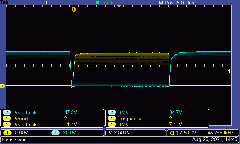
However, when I run the project - the OCP protection trip in the beginning of the process.

I'm seeking for advice on what could be wrong here. Calculation or else. By knowing that I have internal OCP protection I experimented with the values and gain and managed to run the lab, but nothing close to the calculations.

  • Hi Georgi,

    USER_ADC_FULL_SCALE_CURRENT_A may be calculated incorrectly. Doing some quick calcuations,

    Max VDS_OCP = 0.2V
    GAIN = 20V/V
    SOx delta (from VREF/2) = 0.2V*20V/V = +/-4V --> this will saturate your SOx outputs to the USER_ADC_FULL_SCALE_CURRENT_A (16.5) and exceed OCP limits.

    Solution: Use a lower gain setting (5V/V). SOx delta = 0.2*5 = +/-1V.
    This way, SOx delta doesn't saturate. For instance, if SOx uses bidirectional current mode and VREF=3.3V, then SOx will be in range of (1.65V - 1V) = 0.65V and 1.65+1V = 2.65V. This will not exceed your USER_ADC_FULL_SCALE_CURRENT_A (16.5). 

    Thanks,
    Aaron

  • Hi Aaron,

    Thanks for the suggestions. I continue to suspect something else. And yes - you're right about the full scale current in this scenario. I'll give you more detailed calculations:

    The Amp dynamic range is 1.4V and middle point of 1.65V. We are measuring bidirectional currents. By using 0.01ohm shunt resistor that means maximum of 28Amps (5V/V gain) at the beginning of the saturation region which is 3.3V-0.25V = 3.05V. So the maximum measurable current by using 5V/V gain would be (refV - Vo)/(Gain * Rshunt) = (1.65-0.25)/(5*0.01) = 28 Amps and this is the end of the linear region. In this case - should I set USER_ADC_FULL_SCALE_CURRENT_A (56.0) since the measurable range would be -28 to 28 amps? Quick verification - 28A through 0R01 would show 0.28V * 5V/V = 1.4V + 1.65V (middle point) = 3.05V at the SO output. Right?

    Also the VDS_OCP uses different strategy to measure current across the Vdrain and SH for high side and SH and SL for low side. Correct me if I'm wrong. And this has nothing to do with the motorware settings and amp gains. Well, unless the LS_REF switch is 1 which by default is 0. I use this setting as a general overcurrent protection while experimenting with the other settings.

    Edited:

    I add some oscillograms (the power supply is at 32V in this setup):

    This is Highside/Lowside gate before the motor starts spinning (again lab 1b which is voltage control just to verify the design)
     

    And this is what I see when the motor starts spinning:

    Also this is the current measurement on the SP pin (blue) and SO pin (yellow) on the driver:

    5V/V gain:

    40V/V gain:

    Edit 2: Well, after detailed inspection I noticed the SOB and SOC pins shorted together hence the reason current loop control did not work. But the questions about the gain, motorware setting and the gate voltage behaviour remains.

  • Hi Georgi, 

    In this case - should I set USER_ADC_FULL_SCALE_CURRENT_A (56.0) since the measurable range would be -28 to 28 amps? 

    Yes! Your verification calculation is correct. 

    Also the VDS_OCP uses different strategy to measure current across the Vdrain and SH for high side and SH and SL for low side. Correct me if I'm wrong. And this has nothing to do with the motorware settings and amp gains. Well, unless the LS_REF switch is 1 which by default is 0. I use this setting as a general overcurrent protection while experimenting with the other settings.

    VDS_OCP is the driver's overcurrent protection scheme. VDS monitors compare voltage of VDRAIN-SHx for the high-side MOSFET and SHx-SPx for the low-side MOSFET. Nothing to do with MotorWARE settings/gains, just the differential voltage compared to the VDS_OCP threshold (after deglitch time). Assume LS_REF = 0. 

    Yeah, ensure that SOB and SOC are not shorted together. Are you using all three CSAs for all three phases? If you are not using CSAs, it's always recommended to tie the inputs together and float the outputs. 

    Thanks,
    Aaron

  • Yes, I'm using all the CSAs. Ok Aaron, thank you for your input. I've created a separate topic regarding the slew rate of the gates. We are done here.

    Best,
    Georgi