Hello TI,
I am working with DRV8434 and have a query on my bulk capacitor calculation. In app circuit it is stated 100uF but with out any justification.
My calculation is from a app note of TI for bulk capacitor calculation: SLTA055 app note.
C=1.21*Itr^2*L/V^2.
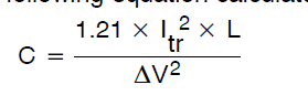
Iload = 1
Lmotor = 1.4mH
Vripple = 3.2 , as battery input is max 32V. C value got is 165uF
Kindly let me know if the formula for the application is right.
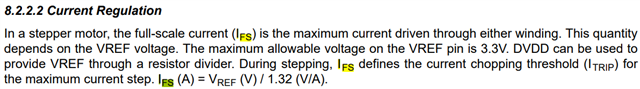
Question 2) The decay mode that must be chosen for the application. Bipolar stepper motor 1Amp and 150 deg rotation. Oil level controllng application.
Question 3) How do i calculate the complete time propagation delay from controller to motor input? Will it depend on decay mode?