This thread has been locked.

If you have a related question, please click the "Ask a related question" button in the top right corner. The newly created question will be automatically linked to this question.

DRV8876: Driver Duty Cycle

Part Number: DRV8876

Hi, 

Using DRV8876PWR for driving DC motor. 

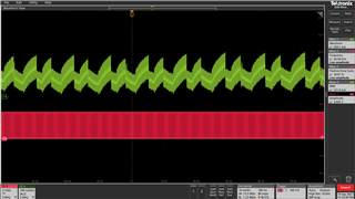
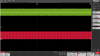
While driving through PWM control method, observed when we provide below 50% duty cycle, the DC motor (with load maximum of 0.2Nm) could not able to run. 

Motor Specification: 

Coil Resistance: 2.5Ohm

Inductance : 16mH

Max. Continuous current : 1.18A

Kindly, provide a clarification on the PWM duty cycle behavior. 

Regards, 

Anjanaa

  • Hello Anjanaa,

    I am happy to be able to help out, and thank you for the provided information. Looking at the datasheet the motor should be perfectly capable of running at lower than 50% duty cycle without stopping provided the voltage is sufficient. Would you mind answering some questions so that I can investigate you request more thoroughly?

    • What switching frequency are you using for your PWM signal?
    • What voltage are you using as Vm to provide power to the motor?
    • Would you be able to share the schematic of your circuit in order to assess any unintended interactions?
    • Are there any faults tripped when you go below 50%? Perhaps an under voltage protection? 
    • Does this happen exclusively with the PWM interface? Would you be able to confirm that this is the case with the PH/EN interface?
    • Would you be able to provide oscilloscope shots of IN1, IN2, OUT1, and OUT2 for the motor at different PWM levels, particularly in the region when it dips below 50% and it stops working?

    If you have any other questions while gathering these data points do not hesitate to write back, I will be happy to assist in whatever I can.


    Best,


    Pedro Arango Ramirez

  • Hi Pedro, 

    • What switching frequency are you using for your PWM signal?
      20KHz

    • What voltage are you using as Vm to provide power to the motor?
      Vm = 19V

    • Are there any faults tripped when you go below 50%? Perhaps an under voltage protection? 
      No fault observed. 

    • Does this happen exclusively with the PWM interface? Would you be able to confirm that this is the case with the PH/EN interface?
      Yes, checked in both PH/EN and PWM mode. Same as in PWM interface.

      Note:

      Also, checked in DRV8876PWPR evaluation board in PWM and PH/EN interface. Observed the same behavior. 

    • Would you be able to share the schematic of your circuit in order to assess any unintended interactions?
    • Would you be able to provide oscilloscope shots of IN1, IN2, OUT1, and OUT2 for the motor at different PWM levels, particularly in the region when it dips below 50% and it stops working?

    In PH/EN mode, while reducing the PWM in EVM board keeping IN1 as PWM and IN2 high. Below 15% the motor could not run.  This is same in our custom design. 

    Whereas in PWM mode, while reducing the PWM in EVM board. Below 55% the motor could not run. This is same in our custom design.

    Attached the scope shot for PH/EN mode, with current (Green) and PWM duty cycle (Pink) for your reference. 

    Working Condition

    PWM below 15% motor not running

  • Hello Anjanaa, 

    Thank you for the promptness and thoroughness of your response. These data is valuable. The fact that PH/EN mode is supporting lower duty cycles than PWM makes me believe that there might be a problem sustaining current through the motor to the point that it can't continue to spin.

    A little bit of background on this: Phase enable mode only supports slow decay, while PWM mode allows for the device to utilize fast decay. Due to this it would be expected for phase enable to sustain lower duty cycles without having the motor stop spinning due to an unbalance between current provided and current decay. 

    To make sure that the lack of spinning below 50% is indeed a current decay issue and not a driver or IC issue, I would like you to do some testing with a resistive load. Use a 16ohm resistor instead of the motor. Then probe the oscillating input and the output to which the resistor is connected. The input should follow the output throughout all duty cycles. If you could provide scope shots of this it would be valuable for evaluation. 

    If the output follows the input at all duty cycles it would support the idea that there is a current decay issue with the motor you are using indicating it is too big. This would mean that in order to drive it you would need a higher Vm or know that your operational range will duty cycles 50%-100% in PWM interface mode. Alternatively if voltage needs to be 19V, and you need the full range of duty cycles you should consider a different motor. 

    Please let me know if there is anything else I can help with or any questions you might have,

    Best,

    Pedro Arango Ramirez.