This thread has been locked.

If you have a related question, please click the "Ask a related question" button in the top right corner. The newly created question will be automatically linked to this question.

DRV8424: Stepper motor not rotating using drv8424 driver

Part Number: DRV8424

Hi ,

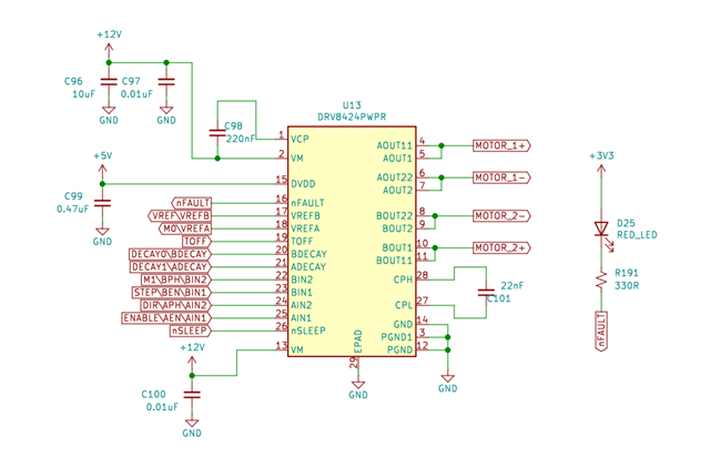
I am using drv8424 motor driver to drive stepper motor named 42HD4027-01 (NEMA 17) . The motor is not rotating but i can hear some noise. I am handling 4 pins from controller namely DIR,STEP,nSLEEP,ENABLE. I am setting nSLEEP ,ENABLE ,DIR high and giving a pwm signal to STEP designed for 10rpm . May i know what is the reason for not rotating . If anyone can support it would be helpful. Please support ASAP'

I have attached pic showing m0.m1,decay0,decay1 connection

Thank you .

  • Hello, Rakshitha,

    What is the VREF pin voltage? Would you check VREF; STEP and output current waveform with a scope and share it there?

    Regards,

    Wang Li

  • Hi, Thank you for the reply

    VREF voltage is 3.3v .STEP signal waveform for 20 rpm  is added below.

  • Hello, Rakshitha,

    1. Do you check it on an EVM?

    2. Since I didn't see the output voltage or current waveform, I am not sure the output is enabled or disabled. Would you measure each pin voltage when you run the motor?

    Regards,
    Wang Li

  • HI,Thank you for the reply 

    1. NO ,I haven't 

    2. Output voltage is not proper aout1,aout2 is getting 12v and bout1 is getting 5v and bout2 is getting 0v 

  • Rakshitha,

    Have you tried more than one IC?  Sounds like this one may have been damaged somehow.

    Regards,

    Ryan

  • No I haven't , Is the procedure what i am following is correct ?? So that I can arrange another IC. The MO,M1, DECAY0,DECAY1 connections i am giving manually is it ok or i should switch to program?

  • Rakshitha,

    It is Ok to add M0, M1, Decay0/1 manually. Let us go through debugging process. In general, we need to:

    1. Check the schematic if it is not an EVM.

    2. If it is thermal issue or noise issue, we need to check the layout. 

    3. Provide the test waveform according to the issue (So far, we don't have it.)

    4. If we cannot have the waveform, measure each pin voltage (or check all register value if it has) to make sure all inputs correct.

    5. Check how many boards do we build? Does all the board have the same issue? Swap the IC between good board and bad board. If only one board, try more IC.

    Please provide enough info to step by step debugging.

    Regards,

    Wang Li

  • Hi,

    These are the output wave forms . I am getting a pwm signal only at bout1 , I have changed IC , I have added our schematic and code here. I have manually connected vref , vrefA/M0 pin to high.

    CODE:

    void motor_start(int DIR)
    {

    HAL_GPIO_WritePin(nSLEEP_GPIO_Port, nSLEEP_Pin, GPIO_PIN_SET);// nSLEEP pin
    HAL_GPIO_WritePin(GPIOB, Enable_Pin, GPIO_PIN_SET);//enable pin
    HAL_GPIO_WritePin(M1_GPIO_Port,M1_Pin, GPIO_PIN_SET);//m1 , m0 is already set
    HAL_GPIO_WritePin(GPIOE,Decay0_Pin, GPIO_PIN_RESET);//decay0 pin
    HAL_GPIO_WritePin(GPIOE,Decay1_Pin, GPIO_PIN_SET);//decay1 pin
    HAL_GPIO_WritePin(Toff_GPIO_Port,Toff_Pin, GPIO_PIN_RESET);//Toff pin


    if(DIR==1)
    {
    HAL_GPIO_WritePin(GPIOB, DIR_Pin,GPIO_PIN_SET );

    }
    if(DIR==0)
    {
    HAL_GPIO_WritePin(GPIOB, DIR_Pin,GPIO_PIN_RESET );

    }

    HAL_Delay(500);

    HAL_TIM_PWM_Start(&htim3,TIM_CHANNEL_2);

    }

    static void MX_TIM3_Init(void)
    {

    /* USER CODE BEGIN TIM3_Init 0 */

    /* USER CODE END TIM3_Init 0 */

    TIM_MasterConfigTypeDef sMasterConfig = {0};
    TIM_OC_InitTypeDef sConfigOC = {0};

    /* USER CODE BEGIN TIM3_Init 1 */

    /* USER CODE END TIM3_Init 1 */
    htim3.Instance = TIM3;
    htim3.Init.Prescaler = 0;
    htim3.Init.CounterMode = TIM_COUNTERMODE_UP;
    htim3.Init.Period = 14994;
    htim3.Init.ClockDivision = TIM_CLOCKDIVISION_DIV1;
    htim3.Init.AutoReloadPreload = TIM_AUTORELOAD_PRELOAD_DISABLE;
    if (HAL_TIM_PWM_Init(&htim3) != HAL_OK)
    {
    Error_Handler();
    }
    sMasterConfig.MasterOutputTrigger = TIM_TRGO_RESET;
    sMasterConfig.MasterSlaveMode = TIM_MASTERSLAVEMODE_DISABLE;
    if (HAL_TIMEx_MasterConfigSynchronization(&htim3, &sMasterConfig) != HAL_OK)
    {
    Error_Handler();
    }
    sConfigOC.OCMode = TIM_OCMODE_PWM1;
    sConfigOC.Pulse = 7497;
    sConfigOC.OCPolarity = TIM_OCPOLARITY_HIGH;
    sConfigOC.OCFastMode = TIM_OCFAST_DISABLE;
    if (HAL_TIM_PWM_ConfigChannel(&htim3, &sConfigOC, TIM_CHANNEL_2) != HAL_OK)
    {
    Error_Handler();
    }
    /* USER CODE BEGIN TIM3_Init 2 */

    /* USER CODE END TIM3_Init 2 */
    HAL_TIM_MspPostInit(&htim3);

    }

  • vref ,vrefA/M0 voltage is 3.3v and Vm voltage is 12v 

  • Rakshitha,

    The schematic looks OK to me.

    "I am getting a pwm signal only at bout1" How about bout2; aout1 and aout2? Would you share the waveform?

    Regards,

    Wang Li

  • hi,

    I have already shared wave forms  its constant 12v waveform for bout2 ,aout1 ,aout2  along with the code . Is my code  correct? . Is their any other way i can contact you because this method is taking a lot of time . 

    Thank you.

  • Rakshitha,

    Please follow the debugging process and send me a private message over e2e. 

    Regards,

    Wang Li

  • Since we discuss it offline, let me temporary close this thread.