This thread has been locked.

If you have a related question, please click the "Ask a related question" button in the top right corner. The newly created question will be automatically linked to this question.

DRV8316: question about current sensor

Part Number: DRV8316
Other Parts Discussed in Thread: DRV8304

Hi team,

My customer will use DRV8316 in their system. We have two questions, can you help to check?

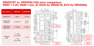
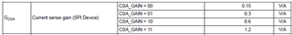
1. Do we have any test results for the noise of the internal current sensor amplifier(CSA) for each gain? How many mV?

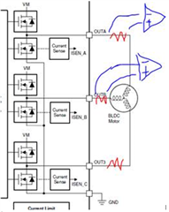
2. The peak current of Motor is 0.2mA for each phase, the output of CSA is 0.24V even we set GAIN to 1.1V/A. Is an external high side current sensor(as shown in the picture below) needed in this case?

3. Do we have any learning material to discuss the how accuracy of current sensors influences the FOC control accuracy?

B&R

Lijia

  • Hi Lijia,

    Is motor peak current 0.2mA or 0.2A? 0.2mA seems very small. 

    1. Noise can occur in the DRV8316's CSAs through a few methods. Ideally the noise should be 0mV for each SOx output, but we have found that there is 4-5 mV of noise due to coupling from internal ground differences. This is more noticeable at higher currents (OUTx > +/-4A), so the mV of noise should be negligible for 0.2A peak current. Also regard in mind possible sources of error in the current sense amplifiers for the DRV8316, I have attached a screenshot below that compares DRV8316 to DRV8304 (internal CSA vs external CSA) showing the possible sources of error:

    2. 1.1V/A is not a valid setting, do you mean 1.2V/A? This is correct if peak current is 0.2A and gain = 1.2V/A, then the SOx should be +/-0.24V delta from VREF/2. You can implement a virtual center tap if needed by adding a resistor on all the phases in parallel to the motor connections and use a comparator to detect BEMF crossings, but if you are using FOC control, then I would not recommending adding resistance in the OUTx path of the motor phases.

    3. For FOC control accuracy, you can follow C2000's application note on Field-oriented control: https://www.ti.com/lit/pdf/sprabz0a. I would ensure that the sensed shunt line currents (for at least 2 phases) is correct so that when performing Clarke and Park transformations, it yields the correct waveforms. General CSA suggestions are that the higher the gain setting, the more the resolution, the lower the range (good for low peak current FOC applications). The lower the gain setting, the lower the resolution, the higher the range (good for high peak current FOC applications). 

    Also note that there are mismatched delay times in integrated FET drivers such as the DRV8316 when running field-oriented control and inserting deadband from the MCU, so you can use Delay Compensation to reduce duty cycle distortion if needed. More info can be found in the app note here: https://www.ti.com/lit/pdf/slvaf84

    Thanks,

    Aaron