


Hi Team,
We would like to ask your your help regarding our customer's inquiry below.
We have use the stepper motor driver chip to drive a unipolar stepper motor with following specification,
Part number: PJB42S33D16
Step Angle: 1.8 degree
Rated Current: 1.2
Resistance 2.4 ohm
Inductance: 2.3mH
We will run the stepper motor with 6.7rps with driving voltage set at 25V and Max current trip at 1.2A.
We have place a infrared light sensor to measure the rotation speed of the stepper motor.
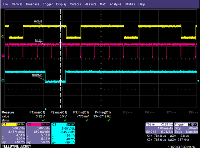
I have used the oscilloscope to measure the HOME and step signal with respect to the DHOME signal (signal from the infrared light sensor. We will notice the HOME and step signals are oscillating as shown in the figure below.
I have measure the phase current across, AOUT1 and AOUT2 and BOUT1 and BOUT2 as shown in the figure below,
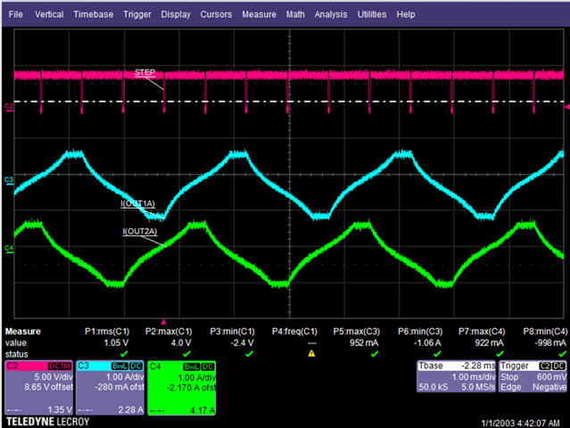
As from the measurement, the current waveform is incorrect and unlike the ideal current waveform for 2 phase full step

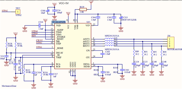
Here is the schematic diagram
Regards,
Danilo
