Other Parts Discussed in Thread: DRV8316, DRV8306
The customer would like to know the following issues:
1. On page 21 of the data sheet, is there a difference between PWM mode 6 and PWM mode 7 in the table PWM_MODE Configuration (continued) when using?
2. On page 21 of the data sheet, does the INHx and INLx pin mentioned in Note refer to the internal pins of the chip? These pins are not in the QFN package pins of the chip.
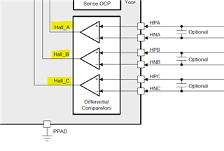
3.Both asynchronous and synchronous debug modes have the Align process, why it isn't the rotor pre-bit processing? The MCT8316Z supports the trapezoidal waveform control algorithm for Hall sensors. For BLDC square wave control with position sensor support, is pre-set processing also required?
4. As mentioned on page 26 of the data sheet, Buck Inductor Mode can support a maximum load current of 200 mA or 50 mA with different inductance values selected, and Buck Resistor mode is used to support load current of less than 40 mA.
However, in the block diagram on page 18, page 19 of the data sheet, there is a description, "Replace Inductor (LBK) with Resistor (RBK) for larger external load or to reduce power dissipation,"
Does the description here conflict with the description on page 26? Why replace the inductance with a resistor when it is overloaded?
5.On page 44 of the data sheet, why is the phase current negative for a small inductor?
6. Is the data check bit in the SDI Input Data Word Format set with the instruction code when the controller sends an instruction to the MCT8316? How is this check bit used and what is the verification mechanism?
7. When will the Advance Angle feature be used?
Please help to check these, thanks a lot!
Best Regards,
Cherry Zhou