Because of the holidays, TI E2E™ design support forum responses will be delayed from Dec. 25 through Jan. 2. Thank you for your patience.

This thread has been locked.

If you have a related question, please click the "Ask a related question" button in the top right corner. The newly created question will be automatically linked to this question.

FOC (field oriented control) with 1, 2 or 3 Shunt Configurations

Hello there,

I have a question about shunt resistors on FOC (field oriented control).

In general, there are 3 different shunt configurations. Single shunt, two shunt and three shunt configuration.

Some TI motor drivers have built-in opamp features for different shunt alternatives.

If we consider the FOC (field oriented control) method while the engine is driving, what is the difference in ride quality between single shunt, two shunt and three shunt configurations?

That is, what are the consequences for three different configurations when driving one engine?

In short, if we try one shunt, two shunt and three shunt configurations separately, what results will we get?

(Assume that the MCU and motor driver used support all shunt configurations, leaving the choice to us)

Thanks.

  • Hi Seden,

    Thanks for posting your question in MD forum.

    I'm assuming the "engine" you are referring to is an Electric motor. Also, I'm assuming you are referring to "Sensorless" FOC.

    The major difference in all three shunt configurations used to sample currents is the Bus voltage utilization. If 100% bus voltage utilization are required by the application, it is recommended to use three shunt resistors to sample the phase currents of the motor. Having single or two shunt resistors limits the bus voltage utilization to be less than 100%. Utilizing bus voltage above the modulation index is called "Overmodulation". Modulation index depends on the type of PWM technique. Modulation index for Space vector PWM is higher than Sine PWM. In the "Overmodulation" region, motors can spin above the rated speed of the motor. 

    Single shunt configuration 

    In sensorless FOC, we need currents of all three phases for accurate speed and torque control. In single shunt configuration, current measurement window will be too narrow at certain time periods causing error in the FOC controller. This error will lead to inaccurate rotor angle estimation. To minimize this error, we need OPAMPS with fast slew rate and low settling time. Also, with single shunt configuration, it will not be possible to spin motors in Overmodulation region. When the motor spins in overmodulation region, duty cycle of low side FETs are too narrow and it is very hard to accurately sense this ultra low duty cycle and control the motor speed. 

    Two shunt configuration 

    The two shunt current measurement technique uses the principle of Kirchhoff's Current Law (KCL) that the sum of the currents into a single node equals zero. By measuring only two phase currents, the third is calculated with KCL. This configuration has the same disadvantage of spinning motors in overmodulation region. Although the two shunt current measurement technique lessens the op-amp's slew rate and settling time requirement as compared to the single shunt measurement, there is a time window where the slew
    rate has to be very large. For the single and two shunt measurement techniques there is no way of getting around the need for a fast and expensive op-amp.

    Three shunt configuration 

    The three shunt current measurement technique is very robust and can achieve overmodulation. Also, slower and cheaper OPAMPs can be used in this configuration. 

    Regards,

    Vishnu.

  • Thanks for your answer.

    What if there is a digital angle encoder like AS5047U (https://ams.com/as5047u) with all these assumptions?

    1) The rotor position information provided for the FOC in this case; Is it derived from an encoder like the AS5047U, rather than the estimates resolved via shunt resistors? In other words, is the encoder providing digital angle information the primary source of information for the FOC?

    2) Will the advantages and importance of the PWM technique and the 1, 2 and 3 shunt configurations used change if there is an external encoder that reports the rotor position in radians via SPI?

    3) In that case, my guess is, is the current reading still necessary with the shunt resistor for the position information required for the FOC? (Maybe, just for validation and testing)

    4) Is it possible to over modulate with an encoder that only provides digital angle information over SPI? (3 shunts not necessary?)

    5) If the encoder rotor position is the most accurate and clear source (I hope my term is correct) based on the FOC by the mcu; Do shunt resistors only help to detect the peaks of the power consumed by the motor, not to exceed the limits and to prevent possible electrical problems? Like detecting something wrong instead of guessing the position information?

    Thanks again.

  • Seden,

    I will get back to you tomorrow. 

    Regards,

    Vishnu

  • 1) The rotor position information provided for the FOC in this case; Is it derived from an encoder like the AS5047U, rather than the estimates resolved via shunt resistors? In other words, is the encoder providing digital angle information the primary source of information for the FOC?

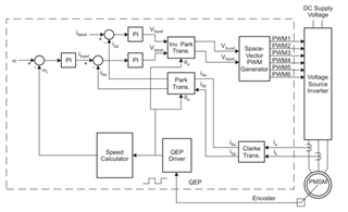
    Rotor position information will be derived from the encoder. However, the phase current information is also required for sensored FOC to control and regulate the phase currents in D-axis and Q-axis as shown in below "Sensored FOC" block diagram.

    2) Will the advantages and importance of the PWM technique and the 1, 2 and 3 shunt configurations used change if there is an external encoder that reports the rotor position in radians via SPI?

    Advantages of the PMM technique and shunt configurations will remain same for sensored FOC. We can expect better performance in terms of the "efficiency" in sensored FOC.

    3) In that case, my guess is, is the current reading still necessary with the shunt resistor for the position information required for the FOC? (Maybe, just for validation and testing)

    Current reading will no longer be required for position sensing in sensored FOC. 

    4) Is it possible to over modulate with an encoder that only provides digital angle information over SPI? (3 shunts not necessary?)

    Overmodulation will still be a challenge with single-two shunt in sensored FOC.

    5) If the encoder rotor position is the most accurate and clear source (I hope my term is correct) based on the FOC by the mcu; Do shunt resistors only help to detect the peaks of the power consumed by the motor, not to exceed the limits and to prevent possible electrical problems? Like detecting something wrong instead of guessing the position information?

    As mentioned in question #1 phase current information is required to control and regulate D and Q axis currents. D-axis controls the flux generated in the stator and Q- axis controls the torque generated by the motor. 

    Regards,

    Vishnu