This thread has been locked.

If you have a related question, please click the "Ask a related question" button in the top right corner. The newly created question will be automatically linked to this question.

DRV8850: Maximum PWM frequency

Part Number: DRV8850

We are trying to smooth out our motor voltage as much as possible. Its a small battery powered system, so the PWM is mirrored in the battery voltage drop. This can cause problems. So our goal is to increase the PWM frequency and increase the SLEW rate to smooth this. In theory, it can blend into a nearly straight line.

What is the maximum PWM frequency? The data sheet says 50k, but is that a hard limit? We've done testing and it works fine at 200kHz. But maybe that is doing some damage we can't see.

  • David,

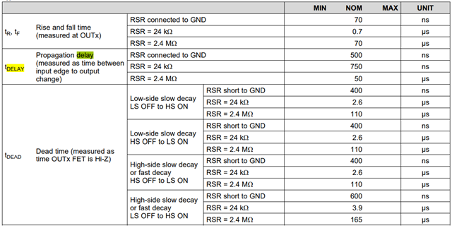
    When the PWM frequency is 50kHz, the cycle time is 20us. To achieve a higher frequency operation, the SR pin needs to be connected to GND.

    In one cycle time (tcycle), tr and tf take about 140ns. Tdead takes about 2x400ns=0.8us. So, the maximum duty cycle without skip pulse is about Duty=(1-0.94us/tcycle). In a switching cycle, the output voltage is Vin*Duty. If the average output voltage is lower enough comparing with the input voltage, we can push the duty cycle a little bit higher.

    For example: 200kHz, the cycle time is about 5us. If tr; tf and tdead takes about 0.94us and have 30% tolerance, the maximum duty cycle without skip pulse is Duty= 1-(0.94us*1.3)/5us= 75.56%. So, if the average voltage is lower than 75.56% of input voltage, we may push the frequency to 200kHz. Also, if we have to count the Rds_on loss on the power FET, the output voltage will be even lower.

    By the way, I didn't see DRV8850 will be damaged with 200kHz PWM frequency.  

    Other other hand, the propagation delay is 500ns which may have 200ns variation. If the PWM duty cycle is very low (output voltage is low), a high frequency could cause a low frequency ripple at output.


    Regards,

    Wang Li

  • Hello Wang,

    Thanks for your detailed answer. I understand what you are talking about, but I think the chip responds a little different than this. We've already tested at 20khz, and with a 300kom SR resistor, and there is no skipped pulses. I think what really happens is the MOSFETs turn on/off gradually, and so it tends to flatten the output. That's what I'm seeing with my analyzer. Still more testing to do though. My main concern was damaging the chip, but seems that's not a problem. I'll let you know what we end up with for final configuration. I'm happy to share analyzer data with you.

  • David,

    Thank you for the update. You can reopen this post when sharing analyzer data.

    Regards,
    Wang Li