This thread has been locked.

If you have a related question, please click the "Ask a related question" button in the top right corner. The newly created question will be automatically linked to this question.

DRV10970: TRAPEZOIDAL MODE HALL PLACEMENT

Part Number: DRV10970
Other Parts Discussed in Thread: DRV8306

Good Morning,

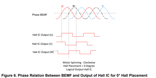
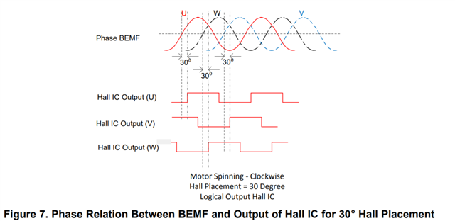
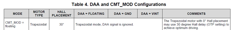
I'd like to ask some clarifications about the concept of the Hall placement (when using trapezoidal mode) concerning the DRV10970 component. I understand the difference between the 0° and 30° Hall placement, but I want to know why it is possibile to configure only 30° placement with trapezoidal mode. Inside the datasheet of the component there is a reference to trapezoidal mode 0° Hall placement (page 17, Table 2, but there is no table); moreover, at page 20, there is another reference to 0° placement (Table 4, see attached figure) but I cannot undestand the meaning of the COMMENTS section: how is it possible to configure the OTP setting for 30° Hall delay?


However, I think the trapezoidal mode with 30° Hall placement is working correctly with my motor, since I can achieve current consumptions which are consistent with the motor specs.

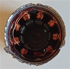
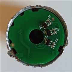
Nonetheless, I wish to understand better. My motor has 3 rotor pole pairs (inner rotor) and 9 stator poles (3 triplets of windings for each phase U,V,W, see attached figure). Hall sensors ICs are spaced of 40°, and they are shifted wrt the stator poles of 20° (see attached figure).


Given such angles, the concept of 0/30° Hall placement is difficult for me to understand and to be applied.

I already tested such motor with the evaluation board of your component DRV8306, and it works correctly. Which Hall placement does the DRV8306 implement for the trapezoidal commutation? 0° or 30° (I would guess 30°, same as DRV10970, since the two behaviours seem identical, but I'd like to understand better how these concepts can be applied to my specific motor and to the drivers I want to evaluate for future use inside my application).

Thank you so much! Kind regards.

  • Hey Alessandro,

    Thanks for you question. To explain 0/30° is related to the BEMF of the system and not the angle separation between the hall sensors on the physical system. I have attached images below for reference. In a 0° hall placement if you look at the zero crossing of the phase BEMF it will align with the latching of the Hall IC output for the same phase. In a 30° hall placement system, the phase BEMF will lead the hall latch by the 30°.

    The reason this is used is to align BEMF voltage with with the phase current of the motor, due to the nature of the inductive coils in the motor the phase current can sometimes  lag behind (depends on the motors inductive characteristics) and adding the 30° hall placement helps align the phase voltage and the phase current. You can learn more about this topic in this TI Precision Labs video: https://training.ti.com/ti-precision-labs-motor-drivers-lead-angle-adjustment?context=1139747-1138777-1139742-1148348

    To summarize if your BEMF voltage and phase current are aligned you can achieve maximum efficiency from your system. Keep in mind that having 0/30° hall placement will not prevent your system from working but make it more efficient. Unfortunately customers do not have access to change OTP settings on the device which is most likely the reason why the table 2 was removed from the datasheet.

    DRV8306 uses 0° hall placement. Trapezoidal commutation is not know for its efficiency so this most likely why you saw similar performance between DRV8306 and DRV10970 and did not see much improvement from the 30° hall placement, or perhaps the inductance rating of your motor is not significant enough to create a current lag between the phase voltage and the phase current of your motor. I hope this helps!

    Best,

    Isaac

  • Good Morning,

    thank you so much for the perfect explanation.

    Regards.

  • Hi Alessandro,

    I'll close this thread. Please let us know if you have additional questions!

    Thanks,

    Matt