


Hi all,
Our design uses a DRV8825 where the current adjustment needs to be controlled by a microcontroller.
While the datasheet does not specifically state a minimum required current for such reference voltage, it does not seem to be too high, considering the examples on the datasheet. I would expected that it will not be more than 50uA if that much.
Our reference voltage is created from a PWM signal passing through an RC low pass filter. It is a simple design that we've used several times before. The MCU pad is configured for a maximum of 4mA. The circuit can be seen below:
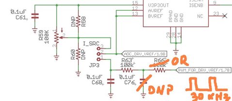
Although there are pads for two RC steps, using only one is enough - so C76 is not populated, and R66 is just a 0R jumper. PWM_FOR_DRV_VREF is a square pulse set to 30 kHz, with low at GND and HIGH at 3.3V. At ~10.6% duty the RC shall output 350 mV, which is the calculated VREF for our motor. This has all been double checked: If we don't insert JP3, voltage is confirmed ~350mA at pin #1 of JP3. ADC_DRV_VREF is a feedback signal to allow the MCU to measure the actual reference voltage.
We've assembled three prototypes. If we install JP3 between pins #1 and #2, the VREF drops to almost zero and the motor does not have enough current to run.
It all seems to point to some sort of shorted hardware... but initial inspection did not show anything obvious. Since it is kind of impossible to order DRV8825 at the present moment, we may test some more after ordering a few evaluation kits and taking the IC out of those - which unfortunately adds one extra uncertainty to an already mysterious condition...
So I guess the initial question is in fact what is the required current for those REF pins, and also to ask if anyone has suggestions regarding the issue.
Thanks!
Bruno

