This thread has been locked.

If you have a related question, please click the "Ask a related question" button in the top right corner. The newly created question will be automatically linked to this question.

DRV8718-Q1: DVDD vs. PVDD power up sequence

Part Number: DRV8718-Q1

Dear expert,

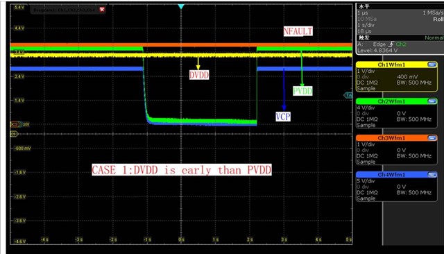
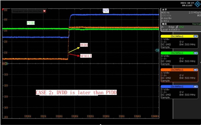
During debug, We found there is no output for VCP if DVDD power up before PVDD. And there is normal 20V output at VCP if PVDD power up before DVDD

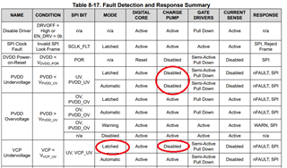
Is it as expected? I cannot find this requirement in the datasheet.

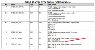
If no, could you guide us how to fix it?

Great thanks

  • Hi Ryan,

    Are you testing this on our DRV8718-Q1EVM or your own hardware?

    Can you share a screenshot of VCP, DVDD, PVDD, and nFAULT for the case when VCP has no output. Set the trigger to rising edge of PVDD and take a zoomed out and zoomed in waveform near the point when PVDD rises?

    Has this issue been observed in other ICs using similar hardware?

  • Pablo,

    It's customer designed board.

    It happens with all five boards under test.

    We will capture signal and send to you soon.

    Great thanks

  • Pablo,

    Pls see attached picture.

    Comment: All signal 0V is at 0V in screen. NO offset. All signal are with different V/div in screen. PVDD=12V.

    Case 1: DVDD is before PVDD. Bad VCP. VCP(blue curve 5V/div)  jump from 0V to around 10.5V  when PVDD comes up. (My apology for my first report. It is not VCP no output. It is VCP is only 10.5V output. VCP is expected as 22.5V)

    Case 2: PVDD is before DVDD. Good VCP. VCP(blue curve 5V/div) jump from 12V to 22.5V when DVDD comes up.

  • Hi Ryan,

    Than you for sharing the information. There doesn't seem to be a fault latching that is causing the VCP to be disable. I think this may be a logic issue caused by the power sequence. The logic circuit which controls the charge pump regulation may not become enabled when DVDD is supplied before PVDD. Just to confirm, was nSLEEP HIGH in Case 1?

    I will investigate with our internal team if this is expected behavior. In the customer's design, will DVDD always be supplied before PVDD?

  • Pablo,

    nSLEEP is pulled up through 4.7Kohm to DVDD.  So it becomes HIGH with DVDD together.

    In customer current design, DVDD is always before PVDD. They can change it in their new design. But they need a solid explanation first.

    It seems 10.5V boost is always active. For case 1,  VCP=10.5V+0V. For case 2, VCP=10.5V+PVDD.  

    Looking forward your help

  • Ryan,

    Understood. We will investigate this issue and get back to you once we find an explanation. Please allow us 48 hours to do our investigation.

  • Hi Ryan,

    I am reviewing your post. Thank you for your summary.

    I am guessing one scenario in customer's case 1. Once PVDD goes down, charge pump is disabled or VCP_UV(under voltage) fault is detected. Once charge pump detect VCP_UV, that fault is not cleared automatically in default setting. As a result, VCP_UV fault condition remains therefore charge pump keep disabling due to VCP_UV fault.

    -Can they set VCP_UV_MODE register bit as "Automatic recovery" then try case 1 again?

       1. Power up both VDD and PVDD. set VCP_UV_MODE =1. 2 turn off PVDD. 3. turn on PVDD.

     Hopefully issue goes away with this sequence.

    If VCP is still disabled, send CLR_FLT in IC_CTRL1=1. It clears fault condition by SPI. VCP may start working.


    Can we have customer's schematic?

       ->Sometimes customer connect external circuit on VCP pin. And would like to double check for charge pump capacitors.

     regards

    Shinya Morita

  • Shinya,

    Great thanks for your suggestion. Customer is testing and will feedback to you later.

    I will forward sch to you through email.

  • Hi Ryan,

    I got schematic via email.

    Thanks,

    regards

    Shinya Morita

  • Pablo, Shinya,

    With "Automatic recovery" setting, the problem is solved. 

    Great thanks for your help!

  • Good to know we could resolved the issue. Thanks.