This thread has been locked.

If you have a related question, please click the "Ask a related question" button in the top right corner. The newly created question will be automatically linked to this question.

BOOSTXL-DRV8323RS: F280025 Universal Lab

Part Number: BOOSTXL-DRV8323RS
Other Parts Discussed in Thread: LAUNCHXL-F280025C, DRV8323, CSD88599Q5DC

Hello,

I am using the BBOOSTXL-DRV8323RS + LAUNCHXL-F280025C om the Universal Lab Code.

Basically, It is triggering the Module Overcurrent  Flag @ 2.78A (phase current).

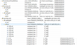
 I checked the drv settings: 

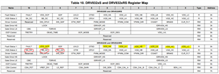
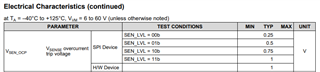
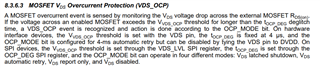
    drvicVars_M1.ctrlReg05.bit.VDS_LVL = DRV8323_VDS_LEVEL_1P700_V; 

    drvicVars_M1.ctrlReg05.bit.OCP_MODE = DRV8323_AUTOMATIC_RETRY;

    drvicVars_M1.ctrlReg05.bit.DEAD_TIME = DRV8323_DEADTIME_100_NS;


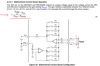
    drvicVars_M1.ctrlReg06.bit.CSA_GAIN = DRV8323_Gain_10VpV;        

    drvicVars_M1.ctrlReg06.bit.LS_REF = false;

    drvicVars_M1.ctrlReg06.bit.VREF_DIV = true;

    drvicVars_M1.ctrlReg06.bit.CSA_FET = false;

 It looks like just the VDS level is set for 1.7V, I tried the 1.88V (maximum), and it still triggering @ 2.78A (phase current).

 My target is to run @ 5A per phase.

Can you help me?

  • Hi Orlando, 

    Thanks for posting your question to the e2e forum - and sure, we are happy to help on this. 

    I am investigating this now, and will try to get you an answer by early next week at latest. Possibly an answer today. 

    Thanks and Best Regards,
    Andrew

  • Hi Orlando,

    Turns out that I can get this answer out to you today - please see the below information, and let me know if this helps clarify how the OCP features work, and also what next steps to try out. 

    The first thing I want to confirm with you is which type of overcurrent (OCP) fault is happening

    • in our system, there are two types of OCP fault monitoring:
      • Current sensing 'SEN_OCP' which reports faults to the 'SA_OC, SB_OC, and SC_OC'  register bits circled in red on the register map
        • this involves the current shunt amplifiers to detect motor phase current flowing through the Rsense resistors 
      • Vds sensing 'VDS_OCP' which reports faults to the 'VDS_HA/B/C and VDS_LA/B/C' register bits highlighted in yellow. 
        • this involves monitoring the voltage drop between drain and source of each external MOSFET, and relies on the MOSFET's Rdson value 
    • Question: can you help check these SPI registers and let me know which ones show up as a fault bit = 1? 

    In the case of the 'SEN_OCP' type coverage, let's take a look at your current settings and the EVM parameters. 

    • Please refer to datasheet section '8.3.4.1 Bidirectional Current Sense Operation' 
      • it looks like you are using bidirectional current sense mode, since your code setting for VREF is 'VREF_DIV = true;'
      • this section will explain how the current sense feature works, given by the equation (3) in the image attached 
    • your CSA gain setting is 10V/V, and the Rsense resistor looks like it is 7mOhms, according to the schematic 
    • Question: What is your input voltage on the VREF pin? 
    • Question: when you monitor the current shunt outputs (SOA, SOB, SOC), what voltages are you seeing?
      • what about the voltages observed on SPx and SNx? 
      • if you have some waveforms to share on this, it may help debug the situation.
    • Question: what is your 'SEN_LVL' setting for the current sensing overcurrent trip voltage? (see image below) 
    • Debug action: My suggestion is to try out different settings for CSA gain, VREF input voltage, and SEN_LVL trip threshold according to the datasheet information and the equation below

    In the case of 'VDS_OCP' type coverage, the highest 'VDS_LVL' setting is 1.88V like you mentioned.

    • checking the MOSFET 'CSD88599Q5DC' Rdson value as being only ~2mOhm, 
      • you are most likely not triggering a VDS-type OCP, since:
        • V=I*R has 1.7V = I * 0.002, resulting in Itrip = 850A for this specific MOSFET on the EVM
        • I think you can use a much lower setting for this in general, since VDS_LVL=0.06V will result in an OCP trip point of ~30A for this MOSFET

    Best Regards,
    Andrew

  • Hi Orlando,

    Just checking up on this e2e thread - do you still require help on this debug?

    Please let me know if the information below has helped resolve the problem, or if there are still some lingering questions or new concerns that you'd like help on .

    Thanks and Best Regards,
    Andrew

  • Hello Andrew,

    Yes, I am trying to collect the info you requested. Give me couple of days.

    Regards,

    Orlando

  • Hi Orlando,

    Understood and thanks for the update

    Thanks and Best Regards,
    Andrew

  • As you see above the OvercurrentModule is triggering, but not flag is set.

    Also, nFault is always @ High, so not tripping from the DRV.

    Checking @ TI code it say it is a hardware flag, but it call ePWM_TZ trip zone.

    Do you know what is that? how this is triggered?

    Also, see below the PWN overshoot and oscillation, is it ok or can generate the Module overcurrent?

    Top is the PWN, middle is the phase current lower is the nFault pin.

  • Hi Orlando,

    If you are not seeing nFAULT go low, then you likely hitting a software overcurrent event rather than an OCP event detected by the DRV8323. Please check your user full scale current settings and gain settings to ensure you have the correct current limits for the application. Trip zones may occur if a software fault occurs from the F280025C. 

    I can forward to C2000 for further support. 

    Thanks,
    Aaron

  • Setting the right values according to your motor in "user_mtr1.h" file. You can increase the value USER_MOTOR1_OVER_CURRENT_A for the over current threshold, but the value must be lower than USER_M1_ADC_FULL_SCALE_CURRENT_A * 0.495f.

    #define USER_MOTOR1_MAX_CURRENT_A          (6.0f)           // A

    #define USER_MOTOR1_OVER_CURRENT_A         (6.5f)           // A

    You might have to follow the user's guide to identify the motor parameters if you are using a new motor which is not listed in "user_mtr1.h".

  • Hello,

    After long investigation it shows up the CMPSS unit is triggering with mosfet switching noise. I set the Filter to 32 samples 32 trigger points to be able to run the motor.

    I believe I will need to disable the CMPSS completely.

  • Yes. You might change the CMPSS configuration for the digital filter, but don't recommend that the CMPSS is disabled, it is used for over current protection.

            // Configure digital filter. For this example, the maxiumum values will be
            // used for the clock prescale, sample window size, and threshold.
            CMPSS_configFilterHigh(obj->cmpssHandle[cnt], 32, 32, 30);
            CMPSS_initFilterHigh(obj->cmpssHandle[cnt]);

            // Initialize the filter logic and start filtering
            CMPSS_configFilterLow(obj->cmpssHandle[cnt], 32, 32, 30);
            CMPSS_initFilterLow(obj->cmpssHandle[cnt]);

  • Thanks, I will run more to check more results