This thread has been locked.

If you have a related question, please click the "Ask a related question" button in the top right corner. The newly created question will be automatically linked to this question.

DRV2604L: Output issue

Part Number: DRV2604L
Other Parts Discussed in Thread: DRV2604

Hi Expert, 

Mt customer have an issue of output waveform.


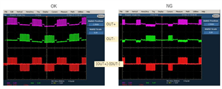
It is occurred by some motors, They have OK motor and NG motor even if same motor part#. They tried to replace another motor, Then, this issue was improved.

Also this issue have often occurred at low temp condition. (At 0C, 2/6 pcs NG)

Could you please give me your advice for the reason of this waveform?

What motor characteristics depend on this issue?

Thanks

Muk

  • Hi Mukuno-san.

    Did all of these LRAs pass Auto-calibration? I recall facing a similar issue with you near the end of last year.

    I recall that the issue occurred during braking and that adjusting the FB_BRAKE_FACTOR lower improved it. Is this issue similar or showing different symptoms?

    Regards,

    Arthur

  • Hi Brown-san,

    Thank you for your support.

    Yes, it passed  Auto-calibration.

    This abnormal waveform was occurred at driving LRA motor. (not braking)

    After this issue, if they keep to drive LRA motor, this issue is improved. Then, occurs again after driving for a while. (don't have trigger event)

    Also this issue have often occurred at low temp condition.

    It seems to be depend on any motor characteristic. but, customer want your advice about what characteristic of motors is affecting to this NG waveform.

    Could you please give me your advice for the reason of this waveform?

    What motor characteristics depend on this waveform? do you have any guess about root cause?

    Thanks

    Muk

  • Hello Mukuno-san,

    Can you please share the part number/datasheet of the LRA

    Can you also share and register settings that have been modified from the default value.

    It looks as though the auto resonance algorithm is not tracking the LRAs frequency correctly

    Regards,

    Arthur

  • Hi Arthur-san,

    Part# : PMV-1040-K02

    Register setting 

    Thanks

    Muk

  • Hi Mukuno-san

    Can you share the resonant frequency and impedance of the LRA? I am not able to find that LRA part number

    From the register setting I notice you have changed some parameters from the defaults. can you please attempt the following and see if there is an effect on the issue?

    set IdissTime = BlankingTime = 5*Le/Re

    where Le is the LRA inductance, and Re is the LRA DC resistance

    Leave loop gain as default value

    Run auto calibration

    It appears as though the auto resonance algorithm is loosing track of the LRA frequency due to the physical parameters of the LRA changing due to temperature. parameters such as IdissTime, BlankingTime and Loop Gain will affect how this algorithm behaves.

    Regards,
    Arthur  

  • Arthur-san,

    LAR motor

    Inductance : 496uH to 992uH (avg 858.4uH) @1kHz

    Resistance : 13ohm +/-10%

    Sorry, I want to correct the device name, it is DRV2604(null).

    IDiss time/Blank time is maximum value "3" (75us)  that can be set maximum available value of DRV2604(null).

    Also, they have already calibration with maximum value. 

    Also, customer found the difference of motor characterization between  frequency and vibration width. (At sine waveform)

    NG motor#1 (issue was occurred under 1.8V condition)

    NG motor#2 (issue was occurred under 1.0V condition)


    OK motor (reference)

    It seems to be depend on the motor characterization.

    Can they adjust any registers in driver device side for improvement this issue?

    Could you please advice for device side adjustment? 


    They want to know about control method to track the resonance point correctly.

    Thanks

    Muk

  • Hi Mukuno-san

    In the case where the DRV is unable to track the actuator we must look deeper into the auto calibration routine.

    from auto calibration the values that are significant to this specific issue will be IDISS_TIME, BLANKING_TIME and the Loop Gain.

    From the register setting you shared the Loop Gain in the customers configuration is 'High" can you ask the customer to lower this value to medium(default) or low, and rerun the autocalibration?

    A higher loop gain can contribute to instability in the system. this is mentioned in the datasheet

    Regards,

    Arthur

  • Hi Arthur-san,

    Customer try to change Loop Gain from 2 to 0. 

    They found a little bit improvement motor waveform. (not fully solved)

    Datasheet is described as below,

    "LOOP_GAIN[1:0] — A value of 2 is valid for most actuators."

    Also, the default value of Loop gain is "1"

    Please tell me which characteristics of the motor should determine this value. (how to select this value?)

    Thanks

    Muk

  • Hi Mukuno-san

    I will be meeting with one of our haptics experts tomorrow to discuss your questions. 

    I am also unclear on how to calculate the values such as Loop gain, It may be the case that these values where found empirically, and that there isn't an equation.

    I will post back tomorrow evening Dallas time.

    Regards,

    Arthur

  • Hi Mukuno-san.

    The selection of parameters such as LOOP_GAIN and FB_BRAKE_FACTOR from the customers perspective cannot be calculated. the Loop gain parameter is not directly related to a numerical gain, but rather it helps the auto calibration routine determine which gain values to select. The reason for this is that the closed loop operation has multiple stages of gain in the forward path and the feedback path. one of those gain factors is the relation between the LRA driving voltage, and the Bemf that is generated from that voltage. This is a parameter that isn't given by LRA manufactures

    For your own intuition you should understand that increasing Loop gain will increase the drive strength to the actuator, at the risk of instability, a value of 1: medium or 2:high should be used as the default, and only deviate from that when it is necessary.

    the same can be said for FB_BRAKE_FACTOR. values from 2x-6x should be chosen as default and not be changed unless deemed necessary.

    Regarding the issue at hand, I talked with our expert about this and I would like for you to try adjusting the DRIVE_TIME[4:0] field. from the register settings you shared above the DRIVE_TIME[4:0] field is set as 0x1A or 161 Hz. and from the resonant frequency plots you showed above the resonant frequency appears to closer to 170-175Hz in many cases. can you try lower values, perhaps 0x19 - 0x16. Due to the way that the DRV uses the DRIVE_TIME[4:0] field to lock onto the frequency of the LRA this may help with stability.

    Unfortunately selecting the right values to optimize across LRA, temperature and voltage will require a certain amount of cut-and-try as well as validating them across a sample size (~10) of LRAs.

    Regards,
    Arthur

  • Hi Artur-san

    Thank you for your comment

    Unfortunately, customer could not see any improvement when they try to adjust DriveTime to 0x18(170Hz).

    If you have any knowledge about DriveTime setting, which is better, lower frequency or higher frequency than the resonant frequency (F0), would you please give me your advice?

    Thanks

    Muk

  • Hello Mukuno-san,

    Arthur is out of office for a few days meanwhile, give me some time to read through the back and forth and see if I can offer feedback.

    Best Regards,

    Carson

    LPA Apps Engineer

  • Carson-san, Arthur-san,

    Additional information about auto calibration results between distorted sample and normal sample.

    Could you please give me your advice for how to adjust?

    A_CAL_COMP value: distorted sample > normal sample

    A_CAL_BEMF value: distorted sample(other than Sample4) < normal sample

    BEMF_GAIN valuedistorted sample < normal sample

    Also, could you please let me know about previous question

    If you have any knowledge about DriveTime setting, which is better, lower frequency or higher frequency than the resonant frequency (F0), would you please give me your advice? 

    Thanks

    Muk

  • Hello Muk,

    Thanks for providing that additional info, Arthur might be back in office tomorrow. If he isn't Ill make sure to give commentary by end of day.

    Best,

    Carson

  • Carson-san,  Arthur-san,

    Do you have any update?

    Muk

  • Hi Mukuno-san.

    the DRIVE_TIME value is theoretically more stable if it is selected to be a higher frequency than the F0. The reason for this is the energy is inserted into the LRA quicker and this allows more time for the DRV to detect the zero crossing of the back EMF. If you select a value for DRIVE_TIME that is lower frequency than F0 it is possible that the DRV will miss the zero crossing point. 

    I am still looking into the collected data you shared. I will respond next week as we have a holiday thur-fri.

    Regards,

    Arthur

  • Arthur-san

    Do you have any update?

  • Hi Mukuno-san,

    I am running low on ideas for what can be done in this case. 

    I notice from the calibration results that you shared that the BEMF_GAIN for the distorted actuators is set to 1

    was this auto calibration performed at room temperature?

    It might be the case that the auto calibration routine selects 1 for this actuator at room temperature, but at cold temp the LRA becomes stiff and the BEMF is too weak to be detected with BEMF_GAIN setting of 1

    Can you manually program the BEMF_GAIN to a higher value? or perhaps run the auto calibration when the LRA is cold (near 0 C)

    Regards,

    Arthur

  • Hi Arthur-san,

    They have done auto calibration at room temp.

    They try to do it at cold temp. I will share you update, if they get the results

    Thanks

  • Mukuno-san,

    It may also be valuable for the customer to measure the acceleration of the actuator when performing these cold temperature tests. 

    using an accelerometer such as this https://www.ti.com/tool/DRV-ACC16-EVM 

    This test could determine if the LRA has frozen and stopped moving, in which case it would be expected that the algorithm would not be functioning correctly.

    Regards,

    Arthur

  • It is closed, because customer is considering open loop.