


Hello,
According to the datasheet, it seems that when you have to refresh the state of the valves, meaning you have to write inside the data register, the enable pin needs to be logic low and in this case all the outputs are disabled.

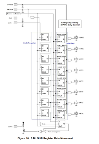
Is this correct understanding? Looking at the block diagram on page 15 the enable is the input of the AND gate to drive the output MOSFET, and it is not involved in the data register read or write.
If I am understanding correctly, this means that when you change the state of a single valve, you need to disable all the others and this could be a big issue for my customer's application.
Thanks in advance!
John

