Other Parts Discussed in Thread: C2000WARE, DAC128S085
Hello
I think, I need some advice, how to do a motor identification .
I have
- LauchXL F280049C
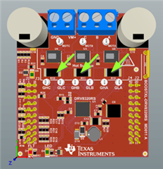
- BoostXL DRV8320RS
- MotorControSDK 3.03.00.00
- instaspin_spruhj1i.pdf
- InstaSPIN Projects and Lab User's guide V1.00.00.00 pdf. Instaspin FOC labs 01-13
- I am able to run / identify a "simple" motor (like a drone motor) successfully by executing LAB05 from C:\ti\C2000Ware_MotorControl_SDK_3_03_00_00\solutions\boostxl_drv8320rs\f28004x\ccs\sensorless_foc\is05_motor_id_eabi
- I reduced the Voltage Range and the Current Range of BoostXL-DRV8320 to 29V and 6A and modified user.h accordingly (works fine)
Very good so far.
Now I need to identify "our" motor. It has some "tricky" parameters
- RS = 6.67 Ohms
- ROverL = 31,4
- flux Volt/Hz = 0,007
- 1 pole pair
- operating speed 9000 RPM -> 33000 RPM = 150Hz -> 550 Hz
- CANNOT be detached from load (it is a pump)
- has VERY little inertia
- has a high startup torque
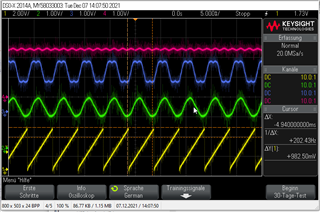
I was able to run "motor identify Lab exercise" up until "EST_STATE_RAMPUP". (Operating-Point 150Hz). Motor is running. A Value for Flux Volt/Hz is measured during rampup and it is fairly stable.
When finished, the motor immediately stops. I cannot tell, if this is during "EST_STATE_CONSTSPEED" or during "EST_STATE_RATEDFLUX_OL" or "EST_STATE_RATEDFLUX"
What options do I have to identify Lq and Ld manually?
Is there a more detailed description, what the estimator is doing during motor identification and to find out, why it stopped immediately after ramp-up? Is there a way to stop the estimator at a certain state to find out, which step is causing the problem?
Furthermore:
If I want to run the motor (if identified) I need to do a open-loop startup until the frequency is e.g. 150Hz. How do I do that? Is there a more detailed description, how to tweak the startup process?
In addition: I find it quite difficult to understand, how the flag "userParams.flag_bypassMotorId" is passed to the estimator. How does the estimator know, that it does not need to run a motor identification?
Thank you for your help
Johannes